
November 19, 2026
Joining Carbon Fiber to Metal: Bonding, Fasteners and Joint Design
A reliable carbon-fiber-to-metal joint is designed as a complete load path. Adhesives can distribute load over an area; mechanical fasteners provide discrete attachment points; inserts and hybrid joints combine different functions. The right choice depends on the composite construction, metal, geometry, environment, assembly process and required inspection—not simply on selecting the strongest glue.
Start by identifying what the joint must do and how it could fail. A decorative carbon insert in a metal frame, a removable cover and a bonded tube fitting present different requirements. An attractive seam or a high adhesive data-sheet value cannot establish that the complete assembly will perform as intended.
Define the two materials and the actual interface
For the composite, identify the resin, reinforcement architecture, thickness and surface condition. A woven outer layer may cover a different internal construction, and a chopped-fiber molding is not equivalent to a continuous-fiber laminate. The joint transfers load into that actual structure, not into the word “carbon” on a product description.
For the metal, record alloy, condition and finish. Bare aluminum, anodized aluminum, stainless steel, titanium and coated metal are different bonding surfaces. If an adhesive contacts paint or a decorative film, the integrity of that layer becomes part of the joint. Do not describe the interface as bare metal when it is actually a coating.
Identify which surfaces are available for preparation and inspection. A deep socket may offer useful overlap but make cleaning, adhesive placement and verification harder. A broad flange may simplify access while changing the load path or visible outline. These are design decisions to resolve before choosing the assembly sequence.
Record whether the assembly must be removable, adjustable, sealed, electrically isolated or electrically continuous. Some requirements can conflict. A permanent adhesive bond may suit one task but make service replacement difficult; a fastener may simplify removal while introducing holes and local contact pressures.
Choose the joint concept by its job
| Concept | Potential role | Question to resolve |
|---|---|---|
| Adhesive bond | Transfer load over an overlap or contact area | Can preparation, bondline and cure be controlled? |
| Through-fastener | Provide a defined mechanical attachment | Can the composite accept local bearing and clamp loads? |
| Bonded or molded-in insert | Create a functional attachment interface | How is load transferred from the insert into the composite? |
| Hybrid adhesive-fastener joint | Combine assembly or structural functions | How do the two load paths interact? |
| Removable clamping arrangement | Allow servicing or adjustment | Can contact pressure and movement be controlled without damage? |
3M’s guide to joining composite parts discusses adhesives alongside mechanical attachment and mixed-material design. The useful principle is to evaluate the complete assembly rather than treat adhesive and fastener choices as isolated purchases.
A hybrid joint is not automatically the sum of two independent strengths. Stiffness, clearance, assembly sequence and damage progression influence which path carries load. A fastener added for positioning may not be a qualified backup, and an adhesive added around a bolt may not provide the load sharing imagined by the designer.
State each element’s intended role in the drawing or assembly specification. If a fastener is only a temporary fixture during cure, say so. If it remains as a structural element, define its material, installation and acceptance. This prevents manufacturing convenience from being mistaken for verified redundancy.
Design the load path before choosing overlap dimensions
Describe force direction, moments and the stiffness of the joined parts. Bonded joints can experience combinations of shear, tension, peel and cleavage. A nominally in-plane load can still create local bending if the load paths are offset. The geometry determines more than the apparent area covered with adhesive.
3M’s structural-adhesive design FAQ distinguishes broadly distributed loading from peel and cleavage. Use that distinction to review how load enters and leaves the overlap, rather than assuming every lap joint experiences uniform shear.
A useful first calculation is average shear stress, force divided by nominal bonded area. For a hypothetical 1,000 N force over a 20 mm by 25 mm overlap, the average is 2 N/mm², or 2 MPa. This is an arithmetic illustration, not a design allowable or a predicted failure load for a KeepWin assembly.
The calculation ignores stress concentrations, bending, defects, adhesive behavior and the composite’s local response. It cannot be compared directly with a single data-sheet lap-shear value to approve the joint. Its purpose is to organize the load and area information before the responsible engineer performs the necessary evaluation.
Consider whether a different overlap, flange, socket or balanced arrangement can reduce unfavorable loading. Increasing area without changing a severe peel condition may not solve the controlling problem. Any geometry change must also remain manufacturable, inspectable and compatible with the surrounding component.
Select an adhesive system, not a headline strength
Give the adhesive supplier the actual adherends, finishes, joint geometry, gap, loads and environment. Also state the available assembly time and cure equipment. A material with attractive laboratory properties may be impractical if it cannot wet the surface, fill the intended gap or cure within the permitted process.
Compare properties under relevant conditions. Room-temperature lap shear does not alone describe peel resistance, sustained-load behavior, impact response or performance after moisture and temperature exposure. The adhesive must be assessed as part of the substrate and preparation system that will actually be used.
Working time, fixture time and full cure are different milestones. A part that can be handled may not yet be ready for its design load or environmental exposure. Record the manufacturer’s applicable instructions and the qualified assembly route instead of allowing operators to infer readiness from whether the surface feels hard.
For a two-part product, use the specified mixing and dispensing method. Mixing ratio, temperature, storage and time after dispensing can affect the process. Avoid publishing one universal ratio, cure time or bondline thickness for all carbon-to-metal joints; those values belong to the selected product and validated application.
Also review serviceability. A bond selected for high-temperature durability may require a removal method incompatible with the composite or nearby components. If replacement is expected, plan the joint and repair route before production rather than assuming any adhesive can later be softened or peeled away safely.
Prepare the composite without damaging the reinforcement
The bonding surface must have a controlled condition. Mold release, handling contamination, moisture and weak surface material can interfere with the intended interface. Agree the preparation with the composite and adhesive specialists, using the actual resin and manufacturing route.
TWI’s composite surface-preparation guidance discusses abrasion and peel ply, including the need to assess the resulting surface. A peel-ply impression is not, by itself, proof that a particular adhesive will bond reliably.
Define what material may be removed and how the prepared area is bounded. Aggressive sanding that exposes or cuts structural fibers can change the component while appearing to improve roughness. Surface preparation is not permission to remove an unspecified amount of laminate.
Where peel ply is used, identify the approved product, processing and removal procedure. Treat a change of peel-ply material as a potential process change, not a cosmetic substitution. The final surface and its compatibility with the adhesive matter more than the generic label.
Protect prepared areas until bonding and define the allowable interval and handling conditions in the qualified process. A carefully prepared surface can be recontaminated during storage or fitting. If the permitted condition is lost, follow an approved disposition rather than simply wiping it and assuming equivalence.
Specify the metal surface and finish sequence
Metal preparation should address the actual alloy and surface layer. Cleaning, mechanical treatment, chemical treatment or primer may form part of a qualified route, but no single sequence suits every metal and adhesive. Obtain applicable supplier instructions and verify the intended system.
3M’s adhesively bonded joint design paper explains the problem of contamination and weak boundary layers. The practical implication is to control the interface being bonded, rather than equate a shiny or rough-looking surface with readiness.
Decide whether coating occurs before or after bonding and which areas are masked. A decorative PVD, paint or anodized surface may require a different bonding qualification from bare metal. Do not remove a specified protective layer without reviewing the effect on corrosion protection and the final drawing.
Include the transition between bonded and exposed areas. Masking boundaries, overspray or polishing residue can affect the edge of the joint. The process should identify where adhesive is allowed, where the cosmetic finish must remain intact and how those requirements are verified after assembly.
Use preparation methods appropriate to the facility and materials, with the required handling controls. A chemical recipe from an unrelated technical sheet is not a general instruction for a custom workshop. The approved method should be documented and reproducible without relying on an operator’s undocumented preference.
Control bondline, location and assembly pressure
Define the intended bondline range and how it is maintained. Too little remaining adhesive, an uncontrolled gap or an incomplete filled area can change the joint from the qualified configuration. The relevant dimensions are those after assembly, not merely the nominal CAD surfaces before clamping.
Choose a locating fixture that holds position without forcing the composite into excessive deformation. Clamping pressure must support the specified assembly process; squeezing until almost all adhesive disappears is not a universal method of making a stronger bond. The fixture should preserve the designed gap and alignment.
Spacers, stops or other gap-control features may be useful when approved for the adhesive and geometry. They also become part of the load path and process, so their material and location need definition. Do not add improvised particles or shims without confirming their effect.
Plan adhesive application and escape paths for a socket or enclosed region. Air entrapment, incomplete wetting and excess adhesive in an unintended area are different issues. A visible external fillet does not prove complete internal coverage, particularly where the joint cannot be directly inspected.
Define cleaning of squeeze-out without disturbing the bondline or contaminating nearby surfaces. Check whether the cleanup product is compatible with uncured adhesive, composite resin and metal finish. The final seam should meet the agreed appearance, but cosmetic cleanup must not conceal an unresolved process deviation.
Design fasteners and inserts around composite limits
A bolt transfers load through local contact and clamping. Review hole quality, edge distance, bearing area, laminate thickness and the support beneath the fastener. A bolt strong enough in isolation does not establish that the surrounding composite can tolerate installation and service loads.
For bonded or embedded fasteners, evaluate how the head, flange or insert distributes load into the composite. bigHead’s technical guidance emphasizes installation performance and notes that torque is only an indirect indicator of clamp load. This supports reviewing the whole installed interface instead of copying a generic metal-joint torque.
Specify washers, bushings, sleeves or local reinforcement where the approved design needs them. Their presence is not a universal cure for every joint: they must fit the load path, space and assembly requirements. The acceptance plan should cover installation damage as well as the final fastener position.
Clarify whether the insert is molded in or attached later, and how its position is controlled. Embedded parts can affect molding and local material distribution; later installation can require machining and bonding. The choice should be made with the composite manufacturing route, not treated as an interchangeable last-minute operation.
For serviceable joints, define disassembly and reassembly limits where relevant. Repeated tightening, wear or replacement can alter the interface. A production assembly test does not automatically qualify unlimited maintenance cycles.
Evaluate galvanic corrosion and electrical paths
Carbon reinforcement is electrically conductive, and some metal-composite combinations can form a galvanic couple in a suitable environment. The FAA’s 2007 airframe guidance identifies the issue of unprotected metal contacting graphite composite in a corrosive environment. This is cited for the physical concern, not as a current certification rule for KeepWin products.
Assess the actual metal, exposed carbon, moisture or electrolyte exposure and electrical continuity. Avoid a blanket claim that every carbon-metal assembly corrodes, or that changing to a particular metal eliminates every environmental concern. The materials and service conditions determine the review.
If isolation is required, define the insulating layer, sleeves, washers or other features as part of the complete assembly. An adhesive layer may contribute to separation, but it is not automatically a verified electrical barrier. Conductive fillers, defects, edge contact or a fastener can create a path around the intended isolation.
Review sealing and drainage alongside isolation. Water trapped at an edge may create a different exposure from an open, dry laboratory sample. If a coating provides protection, its coverage, damage and maintenance need consideration. The joint should be evaluated in its assembled state rather than as two separate coated coupons.
Electrical isolation and electrical bonding are different requirements. Some equipment needs an intentional conductive path. State that requirement early so that the corrosion strategy and electrical function can be designed together, instead of one being accidentally defeated during assembly.
Include temperature, moisture and sustained loading
Metal and composite can expand differently, and the composite response depends on its architecture. Temperature changes can therefore create relative movement and stress in the joint. Review cure temperature as well as service temperature; the assembly may acquire residual stresses as it returns from the cure condition.
Describe the temperature range, rate of change and whether loading occurs during exposure. A brief hot-storage condition and repeated thermal cycling under load are different tasks. Adhesive, resin and coating data should be interpreted with their test conditions rather than reduced to one temperature number.
Moisture, fluids and cleaners can affect different parts of the system. Include relevant exposures in material selection and validation. A dry room-temperature test is useful evidence for that condition, but it does not by itself establish durability after the intended environmental history.
Consider sustained load and time-dependent movement where alignment matters. An assembly can meet an immediate strength check and still require evaluation of long-term displacement. Define the relevant duration and functional limit with the design owner instead of treating all adhesive behavior as an instantaneous failure load.
Inspect what the method can actually establish
Visual inspection can check alignment, accessible coverage, squeeze-out, damage and finish. It cannot prove every internal region is bonded or that the joint has achieved its required strength. Record what was inspected and avoid turning a clean seam into a general declaration of structural quality.
Process records provide different evidence: material identity, preparation, adhesive batch, application, assembly time, fixture and cure history. They do not replace every test, but they help establish that the approved route was followed and make deviations traceable.
If nondestructive inspection is required, agree a method with demonstrated suitability for the actual materials, geometry and defect concern. Evident’s bond-testing overview distinguishes several techniques and defect types. Detecting a void or disbond is not automatically equivalent to measuring adhesion strength.
Use witness samples only when their relationship to the real joint is justified. A flat coupon cured alongside a socket joint may provide useful process information without representing its internal adhesive placement or stress distribution. State what the witness demonstrates and what still needs component-level confirmation.
Define acceptance and disposition before testing. If a result is inconclusive, identify the next check or responsible decision rather than labeling it a pass because the part looks sound. Keep appearance, dimensional conformity, process conformity and functional performance as distinct recorded outcomes.
Build a sample plan around the actual decision
Start with unresolved questions: can the surfaces be prepared reliably, can the overlap be filled, does the assembly remain aligned, and does it meet the intended mechanical and environmental duty? Connect each question to a representative sample and a measurable criterion.
| Requirement | Relevant evidence | Inadequate substitute |
|---|---|---|
| Fit and alignment | Finished geometry and agreed assembly check | An unbonded dry fit only |
| Process repeatability | Traceable preparation, application and cure records | One unidentified demonstration sample |
| Mechanical duty | Relevant load case and failure criteria | Adhesive brochure strength alone |
| Environmental durability | Representative exposure and subsequent checks | Dry room-temperature appearance |
| Isolation, where required | Agreed assembled electrical and environmental evaluation | Assuming the adhesive is insulating |
Keep comparisons controlled. If adhesive, preparation and overlap all change, the result can identify a promising assembly but cannot prove which individual variable caused the improvement. Record that limitation and qualify the selected complete route.
Test specimens should represent the relevant material and finish, including the surface that the adhesive actually contacts. A result on bare metal may not qualify the same geometry after decorative coating. Similarly, a different composite resin or outer ply can require renewed evidence.
Use failure observations to choose the next test
When a sample fails, preserve both sides and their orientation before cleaning or separating loose material. Photograph the whole joint and the relevant regions, with identification and scale. The location of damage can help the engineering team determine what additional examination is needed. A single close-up of the most dramatic area may omit the region where the failure began.
Distinguish failure within the adhesive from separation at an interface, failure within the composite, or yielding and fracture of the metal. These descriptions do not by themselves establish the root cause, but they prevent very different outcomes from being recorded simply as “glue failed.” The corrective action for a damaged outer composite layer may differ from the action for an inadequately prepared metal surface.
Relate the observation to the specimen and test setup. Eccentric loading, an unintended restraint or a fixture that damages the part can influence the result. Confirm that the test represents the intended decision before redesigning the product around an artifact of the test arrangement.
Record the measured result, the defined acceptance criterion and the observed mode separately. A high failure load does not automatically make an undesirable failure mode acceptable, while a specimen that never reaches the required condition cannot establish the intended margin. The responsible engineer must interpret the evidence against the actual application.
If the cause remains uncertain, choose a follow-up that can distinguish plausible explanations. That might involve controlled preparation comparisons, a representative section or another suitable examination. Changing adhesive immediately may be unhelpful if the governing issue is substrate damage, geometry or a process deviation.
Keep rejected samples and their records until the investigation is resolved where practical. Approved samples also need a clear identity. The objective is a traceable explanation of what happened and why the selected correction is justified, rather than a collection of attractive specimens with no connection to the production route.
Example: a carbon tube with a metal end fitting
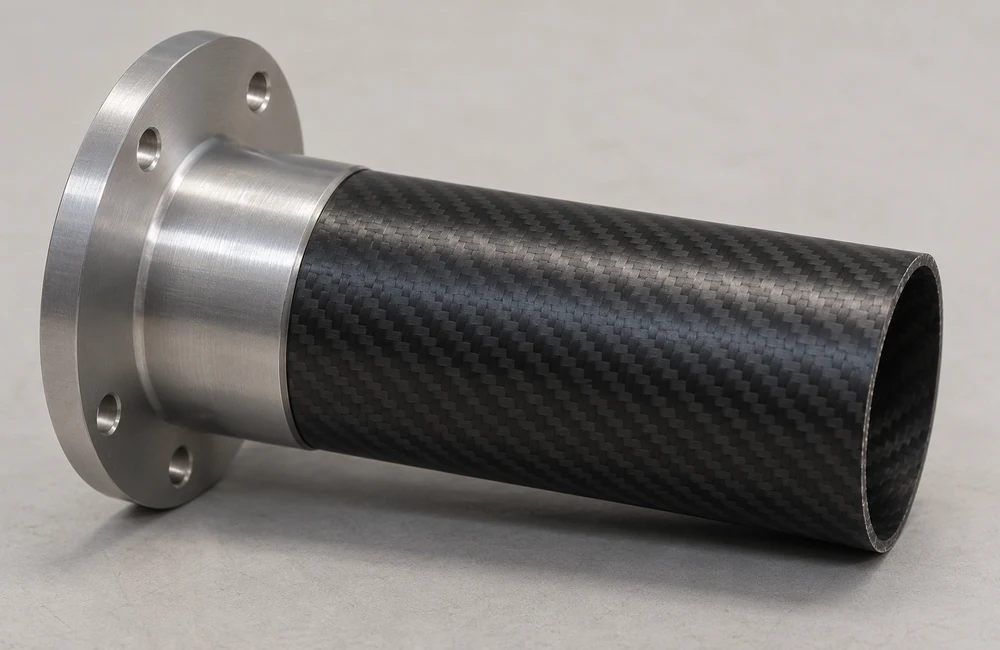
Consider a hypothetical tube-and-socket assembly that must maintain alignment under axial load and temperature changes. Identify the tube construction, metal alloy, finishes, overlap, bondline and intended load directions. A photograph of the assembled fitting cannot reveal these internal details.
First check the dry geometry and access for preparation. Then define adhesive placement and assembly so that insertion does not simply wipe the intended material away from the critical region. The suitable method depends on the selected system; it must be demonstrated rather than inferred from external squeeze-out.
Use a fixture that controls alignment through the required cure stage without forcing the tube into a distorted position. Record the relevant cure conditions and inspect the final geometry after release. A part aligned only while clamped may fail the delivered-state requirement.
Plan the required axial, torsional or bending evaluation according to the actual duty, together with environmental exposure where needed. A successful axial pull does not automatically qualify torque transfer. If failure occurs, identify whether it involves adhesive, interface, composite, metal or another mechanism before choosing the next change.
Finally, agree how repeat production and any repair will be controlled. Preserve the approved material, preparation, application, fixture and inspection basis. This example is a planning exercise, not a report of a KeepWin test or a load rating for the illustrated assembly.
Plan rework, replacement and repeat production
Define what happens when the joint is out of position, incompletely filled or outside the cure record. Some deviations may be assessed; others may require rejection. Do not assume that injecting more adhesive into an unknown gap or reheating an assembly restores the qualified condition.
Removal methods can affect the resin, metal finish and remaining dimensions. The repair plan needs an approved separation, surface-restoration and reinspection route. A part that survives disassembly without visible damage is not automatically fit for rebonding.
For repeat orders, preserve the complete joint specification and approved reference. Changes to adhesive, resin, finish, preparation, supplier or geometry should be reviewed for their effect on prior evidence. A nominally equivalent product name is not sufficient change control.
Compare quotations on the same scope: preparation, adhesive, dispensing, fixtures, cure, inspection, testing and any environmental protection. A low assembly price may leave essential validation outside the offer. Distinguish one-time development from recurring production and clarify responsibility for each acceptance decision.
Frequently asked questions about carbon-to-metal joints
What is the strongest glue for carbon fiber and metal?
There is no universal answer. Select a system for the actual substrates, finishes, gap, loads and environment, then validate the complete joint. A higher isolated strength value does not guarantee a better assembly.
Does adding a bolt make an adhesive joint fail-safe?
Not automatically. Define the fastener’s role and evaluate load sharing, local composite stresses and the relevant failure sequence. A positioning feature is not necessarily a qualified backup.
Can the adhesive alone prevent galvanic corrosion?
Only if the complete isolation strategy is suitable and verified. Conductive paths may exist through fillers, edges or fasteners. Evaluate the assembled joint and its environment.
Can a clean bondline prove adequate adhesion?
No. Visual appearance covers only accessible conditions. Process controls and appropriate validation are needed to establish the required performance.
Prepare a mixed-material project with KeepWin
KeepWin’s carbon-and-titanium product design reference provides a starting point for discussing mixed-material appearance. It does not establish a particular internal attachment method. Confirm the actual component materials, joint and construction for the order.
For non-watch assemblies, provide the drawing, material specifications, finishes, loads, environment, serviceability and acceptance needs. The drawing preparation guide helps organize the brief; the parts manufacturing inquiry starts the review.
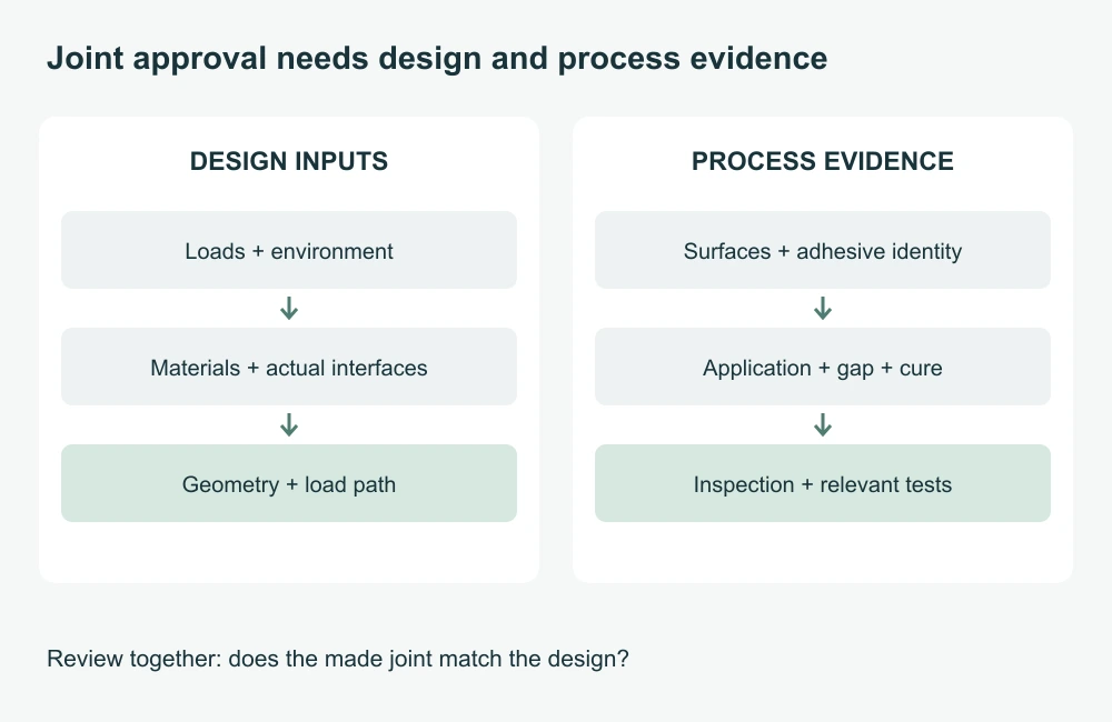
KeepWin coordinates requirements with suitable manufacturing partners. The written proposal must define the actual joining route, production scope and validation responsibilities. An approved joint is a documented system of materials, geometry, process and evidence—not a glue name attached to a product photograph.