
Grip or touch
Map handling regions and the intended feel or deflection. Evaluate a physical sample without assuming skin-contact suitability or a universal wear life.
PARTNER-SUPPORTED MANUFACTURING / MATERIAL INTERFACES
A soft region, rigid substrate or colored layer must be reviewed as a material pairing and a controlled geometry. Make contact surfaces, interface duty and final-state evidence explicit before selecting the offered route.
KeepWin coordinates partner-supported review. Exact material, responsible operations, process availability, dimensions, inspection, commercial quantities and timing are confirmed in the project proposal; no universal capability or certification is promised.
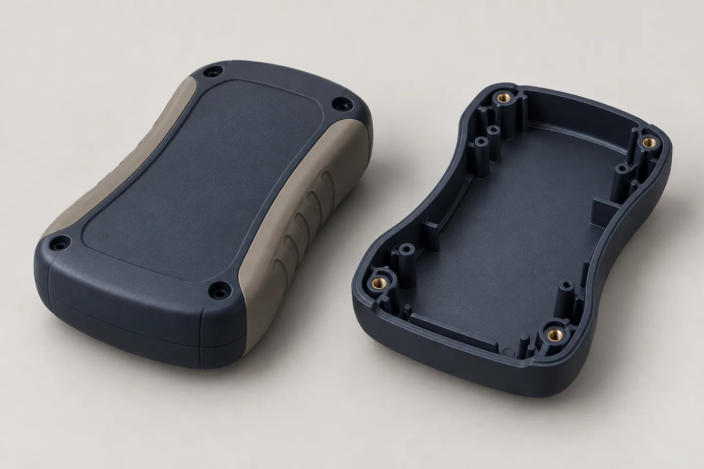
Generated rigid-enclosure and soft-grip design concept. It does not verify substrate compatibility, material formulation, adhesion, contact suitability or an actual customer job.
01 / INTERFACE PURPOSE
A visual contrast, grip surface and loaded interface require different evidence. Do not treat every multi-material model as the same application.
Map handling regions and the intended feel or deflection. Evaluate a physical sample without assuming skin-contact suitability or a universal wear life.
Define boundaries, color and visible surfaces. Agree the actual substrate and viewing reference rather than using a render as a color standard.
Describe loads, contact, movement or sealing intent. The interface needs a relevant requirement and evidence; no default adhesion or retention result is promised.
02 / REGION GEOMETRY
The location and protection of the materials can affect the assembly. Review tooling and sequencing before approving the geometry.
Provide material, condition, revision and dimensional requirements. If supplied by the customer, define incoming acceptance and responsibility.
Show material boundaries, required coverage and transitions. Explain which dimensions or faces govern appearance and function.
Identify interface duty and proposed geometry for review. Do not assume a material pairing always bonds without an agreed design and evaluation.
Mark contacts, holes, threads, visible faces and locating regions that must remain usable. Protection and positioning require confirmation.
03 / MATERIAL COMPARISON
Substrate and overmold formulations have compatibility and processing questions. Exact offered materials should be named in the proposal.
| Item | Provide | Resolve |
|---|---|---|
| Substrate | Grade, condition and supplied geometry. | Actual identity and permitted alternatives. |
| Added material | Formulation, color and functional need. | Compatible offered pairing and evidence. |
| Interface | Load, contact and region boundaries. | Tooling approach and acceptance method. |
| Exposure | Temperature, fluids, light or repeat handling. | Application-relevant evidence and limits. |
04 / TOOLING & HANDOFF
Molding sequence, component supply and handling may differ by project. No universal equipment configuration is implied.
Ask the offer to identify substrate manufacture, transfer and added-material operations. Keep the partner-supported responsibility map visible.
Review how critical faces and substrate position are controlled. Available tooling and protection are proposal-specific rather than default capabilities.
Define incoming condition and how rejected components or assemblies are reviewed. Commercial loss and replacement assumptions should be explicit.
A new substrate, formulation, color or region boundary can change the acceptance basis. Agree who reviews the change and whether another sample is needed.
05 / EVIDENCE
Dimensions, visual transitions and interface performance are distinct checks. Agree the state and method needed for the actual application.
| Question | Agree | Record |
|---|---|---|
| Fit | Final dimensions, datums and mating reference. | Both material and geometry revisions. |
| Appearance | Coverage, boundaries, color and permitted marks. | Physical sample and viewing basis. |
| Interface duty | Relevant retention, load or contact evaluation. | Method, criterion and represented condition. |
| Identity | Materials, operations and lot scope. | Required records and delivery linkage. |
06 / QUOTE PREPARATION
Substrate supply, preparation, tooling, sample work and evidence can create different commercial scopes. Put them beside unit quantity.
Include substrate and added-region files, exact materials, interface purpose, protected features, quantities, destination and mandatory documentation.
Identify substrate supply, tooling, transfer, overmolding, finishing, inspection, records and packing where relevant. Confirm exclusions and defect assumptions.
Approve the pairing, region map and sample evidence before repeat production. Compatibility, MOQ, capacity and schedule remain actual proposal items.
07 / QUESTIONS
The substrate and added material need a shared interface specification.
No compatibility or adhesion is assumed. Review the exact pair, interface geometry, process and evidence.
Supply, incoming condition, location, protection and responsibility require confirmation for the project.
No universal result is claimed. Define the relevant application and the method and evidence required.
Map visible and functional zones and agree boundary, color and mark limits for each.
Only through agreed review of compatibility, processing, fit, appearance and earlier sample evidence.
PREPARE THE NEXT DECISION
Include both material definitions, CAD and drawing revisions, region boundaries, protected faces, interface duty, sample and production quantities, evidence and destination.
sales@keepwinco.comAn enquiry starts a team review. Material, fit, quantity, schedule, operation responsibility and supporting records are confirmed in the proposal; this form does not create an order or an instant price.
Start with what you know. Review your details before sending; no account needed.
Start parts inquiry →Your project is saved securely only when submission succeeds.
General material context only; external references do not certify a finished KeepWin product.
Protolabs - overmolding design context ↗