
Housings & enclosures
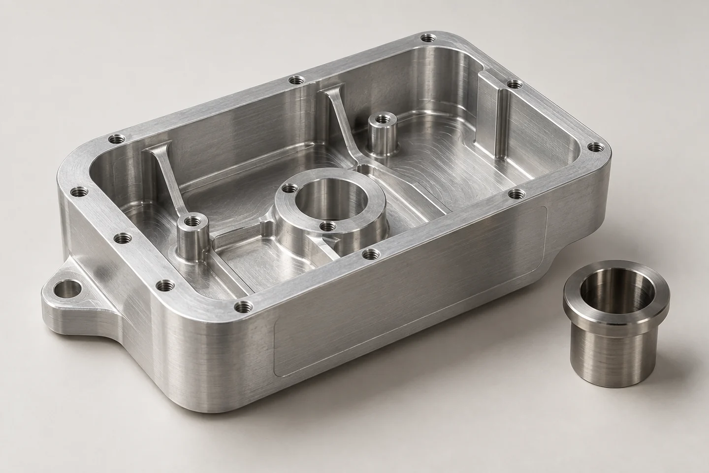
Review pockets, sealing faces, mounting holes and connector openings together. Keep the functional interface distinct from cosmetic surfaces.
PARTNER-SUPPORTED MANUFACTURING
Bring your housings, brackets, pockets and precision interfaces into focus. KeepWin coordinates project review and partner-supported manufacturing around your drawing, material and acceptance requirements.
Process, responsible manufacturing site, sample scope and inspection records are confirmed in the project proposal.
01 / CHOOSE THE PROCESS
Milling uses a rotating cutter to remove material from a held workpiece. It is often considered for prismatic parts, pockets, slots, planar faces and features distributed across different faces. Tool access and workholding still determine feasibility.
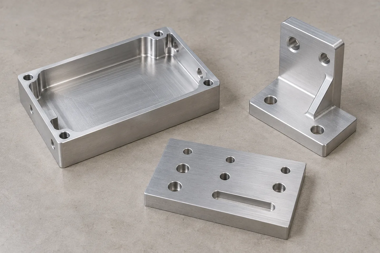
Review pockets, sealing faces, mounting holes and connector openings together. Keep the functional interface distinct from cosmetic surfaces.
Identify load-bearing faces, locating features and the space needed for fasteners. Check whether the part can be held without damaging a finished face.
Features on several faces may require repositioning or a multi-axis route. Relationships between those faces can matter more than any single dimension.
| Decision | CNC milling | CNC turning |
|---|---|---|
| Main motion | Rotating cutter; workpiece is held or repositioned. | Rotating workpiece; tools remove material around its axis. |
| Typical starting geometry | Prismatic stock, plates and blocks with pockets or multi-face features. | Rotational features such as shafts, sleeves, rings and concentric diameters. |
| Features to highlight | Pocket depth, internal corner radius, face access and hole relationships. | Concentricity, diameters, shoulders, grooves and axial features. |
| When both may be needed | A turned body with flats, slots or off-axis holes may need secondary milling or a combined route. The proposal should identify the sequence and responsibility. | |
02 / ACCESS & SETUPS
More axes do not automatically improve every part. Geometry, fixtures, tool reach and inspection relationships guide the route. These are general process options, not a statement of KeepWin-owned equipment.
3-AXIS
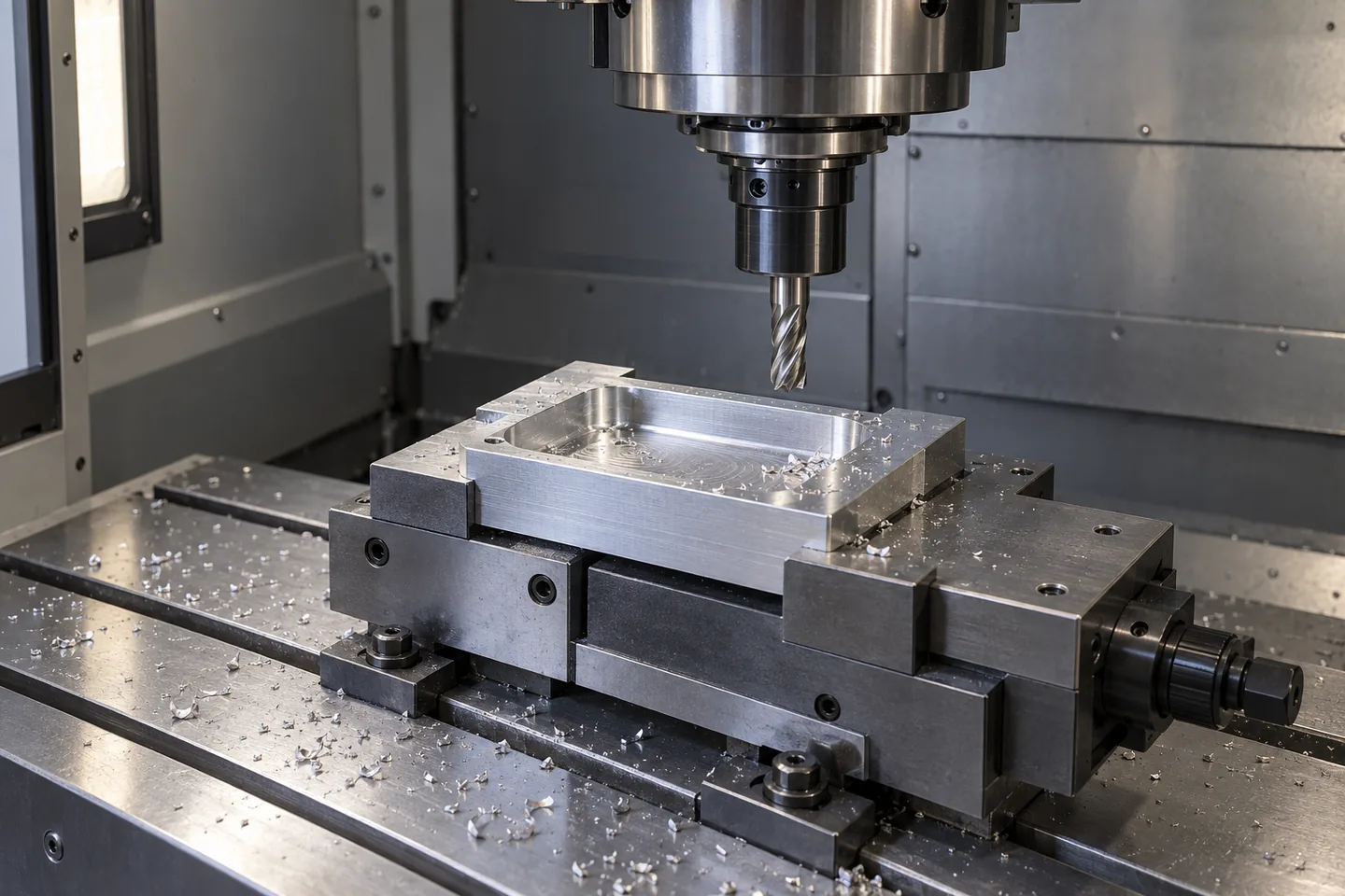
Useful to consider for planar faces, pockets and holes accessible from a fixed orientation. Other faces may need another setup.
Review: setup count, datum transfer, tool clearance and whether re-clamping affects critical relationships.
INDEXED / 3+2
The part or tool is positioned to a different angle before cutting. This can give access to several faces without treating every surface as a simultaneous contour.
Review: fixture clearance, angular features and which dimensions must remain related across orientations.
SIMULTANEOUS MULTI-AXIS
Coordinated motion can be considered for contoured or angled geometry where changing tool orientation is useful.
Review: collision clearance, surface intent, programming and verification effort. Simpler geometry may be more economical.
03 / MATERIAL TRADE-OFFS
Strength, weight, corrosion exposure, finish and dimensional stability can pull the choice in different directions. This comparison supports discussion; actual grade, stock condition and availability must be confirmed.
| Material family | Why consider it | Trade-off to review | Include in the brief |
|---|---|---|---|
| Aluminum | Low weight; many grades are practical for machined housings and brackets. | Alloy and temper affect strength, machining and anodized appearance. | Grade, temper, loading, cosmetic faces and finish intent. |
| Stainless steel | Corrosion resistance and durability for demanding environments. | Grade-specific machinability, weight and surface treatment requirements. | Exact grade, exposure, passivation or finish specification. |
| Carbon / alloy steel | Strength and wear-related applications, depending on grade and condition. | Corrosion protection, heat-treatment distortion and machining sequence. | Grade, supplied condition, hardness and final-state dimensions. |
| Brass / copper | Brass for suitable fittings; copper where conductivity is a design driver. | Alloy-specific strength, machinability, oxidation and surface handling. | Alloy, conductivity needs, thread details and surface requirements. |
| Titanium | Weight-sensitive and corrosion-related applications when the grade fits. | Material and machining effort; tool access and thermal management need review. | Grade, functional justification, critical features and documentation. |
| Engineering plastics | Low weight, electrical insulation or sliding functions, depending on polymer. | Heat, moisture, stiffness, stress and creep can affect geometry in use. | Polymer grade, temperature, moisture environment, loads and inspection condition. |
No substitution is implied. Separate mandatory requirements from alternatives that you are willing to evaluate.
04 / DESIGN FOR REVIEW
Illustrative diagrams below show relationships, not dimensional limits. Feasible radii, depths, wall sections and threads depend on the material, feature geometry, tooling and proposed manufacturing route.
01 / DESIGN CHECK
A rotating cutter leaves a radius at an internal pocket corner. Allow a radius compatible with tool access; if a mating square corner needs relief, show the intended clearance and discuss a suitable relief geometry.
02 / DESIGN CHECK
Deep or narrow cavities can increase tool overhang, reduce stiffness and complicate chip evacuation. Reduce unnecessary depth or open access where function allows; identify any floor flatness or wall relationship that must be retained.
03 / DESIGN CHECK
Slender walls can deflect under cutting or clamping forces. Review wall height, thickness, nearby support and material stiffness together. Do not infer a universal minimum wall thickness from an illustration.
04 / DESIGN CHECK
State thread standard, nominal size, pitch, fit class and required usable engagement. Distinguish usable thread depth from drilled-hole depth; a blind hole needs allowance for tool entry and incomplete threads.
05 / DESIGN CHECK
A fixture needs a stable locating and clamping strategy. Show protected cosmetic faces and critical locating surfaces. A feature hidden by a clamp may require a different setup or fixture.
06 / DESIGN CHECK
Use a consistent datum scheme tied to function. Mark mating fits, positional relationships and truly critical dimensions on the drawing. A 3D model alone may not communicate tolerance, finish or inspection intent.
05 / FINAL-STATE REQUIREMENTS
Decide which faces are functional, cosmetic or both. Material removal and added surface layers can change a fit; final-state requirements should be agreed before machining and finishing are scheduled.
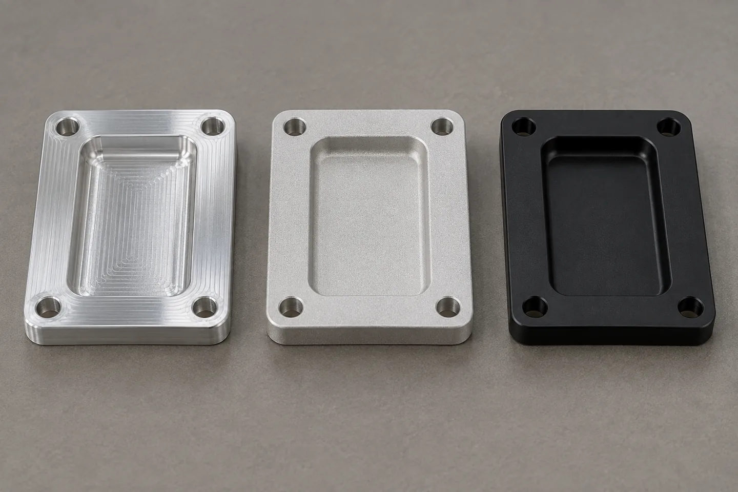
Tool marks can remain. Specify allowed burrs, edge breaks and any edges that must stay functionally sharp. A general “smooth” note does not define a measurable finish.
Define texture, direction and reference appearance. These processes can remove material or round edges; protect fits and agree whether appearance is judged against an approved sample.
Confirm compatibility with the exact material, treatment specification, color and masking. Added layers or converted surfaces need review around holes, threads, mating faces and electrical contacts.
| Area | Question for the proposal |
|---|---|
| Mating fits & threads | Are dimensions specified before or after treatment? Which areas require masking or a finishing allowance? |
| Cosmetic surfaces | What sample, texture direction, color range and viewing conditions define acceptance? |
| Electrical / sealing faces | Which surfaces must preserve conductivity, flatness, texture or seal contact? |
| Verification | Which final-state dimensions and surface properties are inspected, and what records are supplied? |
06 / PROJECT HANDOFF
The agreed proposal defines who performs each operation, what gets approved and which milestone starts the schedule. Sample and inspection scope should be explicit rather than assumed.
Check CAD, drawing revision, geometry, grade, quantities, finish and unresolved questions. Identify the responsible manufacturing route and site.
Define whether samples are needed, which features they validate and the documentation required. Agree changes before work starts.
Approve drawing, material, process, price scope, acceptance criteria and schedule assumptions. Record exclusions and responsibilities.
Follow the agreed route. Review any proposed substitution or design change before accepting it; do not treat it as an automatic equivalent.
Verify the agreed final-state features and records. Confirm packaging, identification, transport and how a discrepancy is handled.
07 / ACCEPTANCE EVIDENCE
Inspection is most useful when it follows the part’s function. Required reports, sampling and material documentation are project-specific; their availability and scope must be included in the quotation.
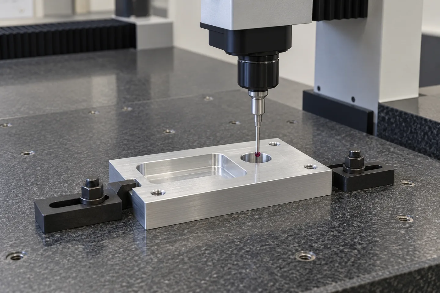
List critical dimensions, geometric relationships, measurement method and the datum reference. Specify whether results apply to samples, a first article or an agreed production sample.
Mark visible faces, permitted tool marks, burr condition and finish references. Agree inspection lighting or viewing conditions when cosmetic acceptance matters.
Identify the grade and required material evidence. State any traceability, treatment records or certification needs explicitly; these are not included by default.
Agree part number, drawing revision, quantity identification, packaging protection and the records that travel with the shipment.
08 / BUILD A USEFUL QUOTE BRIEF
A clear brief separates mandatory specifications from preferences. This helps evaluate a practical route without silently weakening the design intent.
Request separate lines for setup or tooling, unit cost, samples, finishing, inspection and delivery where relevant.
If the design is incomplete, describe the uncertainty. A review can start before every decision is final.
09 / COMMON PROJECT QUESTIONS
This page describes partner-supported manufacturing. The project proposal should identify the responsible manufacturing site, process scope and any partner operations. Do not infer equipment ownership from a sample photograph or a general process description.
These depend on the material, geometry, equipment suitability, finish, inspection scope and current project schedule. Share your requirements for review; no universal numerical limit or delivery promise is stated on this page.
A model communicates shape, while a drawing can define datums, tolerances, threads, finish and acceptance requirements. Send both where available and identify the controlling revision and any unresolved differences.
A conventional rotating milling cutter produces a radius at a pocket’s internal corner. If sharp-corner clearance is functionally necessary, discuss relief geometry or another suitable process during review rather than assuming milling alone will create it.
Only the scope confirmed in the proposal should be assumed. Specify sample quantity, features to verify, required material evidence and report format before approval.
Agree any NDA and sharing permissions before uploading confidential designs. Read our confidentiality and design ownership guidance. You can start with a non-confidential description and arrange the next step with the team.
START WITH YOUR PART
Share the features that matter and the decisions still open. This enquiry starts a team review; it does not create an instant quotation or place an order.
sales@keepwinco.comEquipment, tolerances, size limits, MOQ, lead time, certifications and operation ownership require project-specific confirmation.
General engineering context only. Supplier-specific capacities and commercial terms in external references do not apply to KeepWin.
Sandvik Coromant · milling cavities and tool access ↗Haas · indexed and simultaneous machining concepts ↗Ensinger · plastics and dimensional stability ↗Protolabs · finishing considerations ↗