
November 17, 2026
Machining Carbon Fiber Parts: Drilling, Trimming and Delamination Control
Machining carbon fiber successfully means cutting the reinforcement cleanly while preserving the surrounding composite. A hole can meet its diameter tolerance and still have damaged plies; a smooth-looking edge can conceal separation below the surface. Start with the actual material construction, support the cut, select a suitable composite tool and verify both dimensions and material integrity.
This guide concerns machining cured carbon-fiber-reinforced polymer, or CFRP: drilling holes, trimming contours and checking the resulting features. It does not assume that every black patterned component has the same internal structure. Continuous-fiber laminates, chopped-fiber moldings and composite-metal stacks need different process reviews, even when they share a similar product description.
Identify the material before choosing a cutter
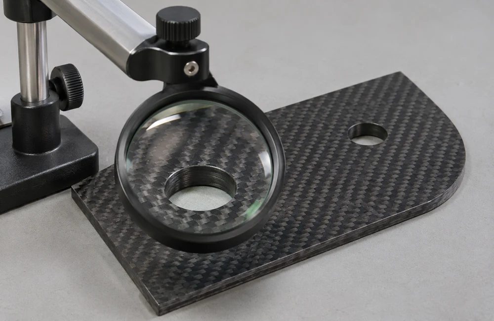
“Carbon fiber” is an incomplete machining specification. Ask for the resin system, reinforcement form, nominal thickness and variation, cure condition and any outer coating. For a laminate, obtain the relevant layup and surface-ply information. For a molded chopped-fiber component, identify the molding compound and manufacturing route. A decorative woven surface does not establish the construction underneath it.
The resin and fibers do different jobs and respond differently to cutting. Fiber direction changes around a contour relative to the tool path, so an edge that cuts cleanly on one side may behave differently on another. This is a reason to inspect the whole relevant profile, not only the straight section that looks best in the sample photograph.
Also distinguish solid laminate from sandwich construction. Drilling through skins and a core creates support and joint-design questions that are absent from a solid plate. Do not approve a sandwich-panel fastening detail from a solid-laminate trial. Inserts, core treatment and bearing loads require their own engineering review.
Record the material revision alongside the drawing revision. If a supplier changes resin, reinforcement, thickness or surface layer, review whether the qualified machining route remains applicable. “Same carbon appearance” is not a valid reason to transfer a cutting program or an acceptance record without checking what actually changed.
Separate delamination, fiber damage and dimensional errors
Delamination is separation between layers in a laminate. Fiber pull-out, uncut fibers, edge chipping, resin damage and dimensional deviation are related inspection concerns, but they are not interchangeable names for the same defect. Calling every rough edge a burr makes it harder to select the right corrective action.
| Observation | What needs checking | What appearance alone cannot establish |
|---|---|---|
| Raised or separated plies | Location and extent of laminate separation | The full subsurface damage area |
| Loose or projecting fibers | Cutting action, tool condition and fiber orientation | That trimming the projections restores integrity |
| Irregular hole wall | Size, form, local breakout and surface condition | Acceptable bearing performance |
| Discoloration or smeared resin | Possible thermal or contamination issues | The exact temperature reached during cutting |
| Correct diameter with damaged exit | Both dimensional and damage acceptance | Overall conformity from the diameter result |
Photograph the condition with a scale, feature identifier and stated view. Record whether the image shows entry, exit or the machined wall. A close-up without orientation may hide that only one face was inspected. Where the acceptance question concerns internal separation, plan a method capable of addressing it.
Do not infer a defect’s cause from one visual symptom. A damaged exit can involve support, tool geometry, wear, feed or material condition. Start from a controlled baseline and change the relevant factors systematically, rather than adjusting several settings until the edge looks better without understanding why.
Why drilling entry and exit need separate attention
At entry, the cutting action can lift or tear surface material. Near exit, the remaining material ahead of the drill has less support, and drilling force can contribute to separation before the fibers are cut cleanly. The practical objective is to control both the cutting action and the support available through breakthrough.
Research into bidirectional CFRP drilling examines exit delamination through thrust and laminate support. Its specialized method is not a universal production recommendation; it reinforces the need to assess breakthrough conditions for the actual part.
Specify which face is the entry face when that matters. If the visible surface or most critical joint face must receive a particular process orientation, include that in the route. Reversing the component to simplify loading can change which surface experiences the exit condition and therefore invalidate an unqualified assumption.
Inspect both ends of representative holes during development. Good entry quality does not prove a good exit, and a clean exit does not establish the hole-wall condition. The sample plan should capture the locations that matter to appearance, assembly and structural function instead of treating one photograph as proof of all three.

Use backing and fixtures as part of the cutting system
A suitable backing arrangement can support the exit region, but it must contact the intended surface and remain effective as holes accumulate. A worn backing plate with a large opening beneath the next hole does not provide the same support as a fresh, closely fitted region. Include backing condition in the setup instructions.
The fixture should locate the part without introducing unacceptable local crushing or bending. Spread loads where appropriate and review thin webs, curved faces and unsupported edges. Clamping harder is not automatically safer: a part can be machined while distorted and move after release, even if it appeared stable during cutting.
Provide clearance for the tool to break through without striking the fixture. That clearance must be reconciled with the need for support rather than left as a late shop-floor improvisation. A replaceable sacrificial layer may be appropriate, but its material, cleanliness and compatibility belong in the process review.
For vacuum workholding, examine available sealing area, cut-through paths and loss of holding force as the contour opens. A small component may become less secure near the final pass. Tabs or other retention features require an approved removal and finishing route; they should not leave an uncontrolled notch in the delivered edge.
Document the setup that produced the approved sample. Support location, loading orientation, backing replacement and release sequence can matter as much as the nominal spindle settings. A fixture photograph helps identification, but the repeatable instructions must state the features that determine support and location.
Choose geometry and tool material for the construction
Composite-specific drills are designed to address mechanisms that differ from ordinary metal drilling. For example, Harvey Tool’s double-angle composite drills target push-out and delamination. That is a tool-design example, not evidence that one geometry suits every laminate, diameter or machine.
Choose the actual tool with its manufacturer or machining specialist using the material, operation, thickness and quality requirement. Clarify whether the recommendation concerns solid CFRP, a sandwich panel or a metal stack. An apparently similar catalog tool may have a different intended exit condition or substrate combination.
Tool wear deserves a planned response because a usable-looking edge can already be producing unacceptable damage. Establish an inspection interval and a retirement criterion during trials. Counted holes or machined length can support the record, but a fixed number copied from another laminate does not guarantee the same quality.
Compare tooling economics using accepted parts, not only purchase price. A more expensive tool can be reasonable if it maintains quality for the required batch, but that conclusion needs application evidence. Include setup, inspection, rework and rejected parts in the comparison rather than assuming either the cheapest or hardest tool is automatically best.
Develop cutting conditions without a universal recipe
There is no responsible single speed-and-feed table for every carbon-fiber component. Start from the tool supplier’s recommendation for the actual material and operation, then verify it on representative stock with the intended support and inspection method. Record diameter, geometry, tool condition, engagement, feed, speed and machine setup together.
Reducing feed may reduce one source of load but can introduce other process issues if the tool is no longer cutting effectively. Increasing speed may improve one observation while increasing temperature or wear elsewhere. Treat parameter changes as hypotheses to test, not as universal rules such as “slower is always safer.”
Pay attention to entry, steady cutting and breakthrough as distinct stages where the equipment permits suitable control. A parameter that works in the supported middle of the cut may not be appropriate at the final plies. The resulting cycle must still maintain tool control and produce an inspectable feature.
Check runout, holder condition and machine stability before attributing every problem to the laminate. A process-development record should include the equipment condition relevant to the trial. Otherwise, a tool comparison may actually compare two different setups, making the apparent result difficult to reproduce.
Do not issue a production release from one successful hole. Include enough representative work to examine variation, tool progression and the relevant geometry. The appropriate sample size depends on the project; it should be agreed rather than invented as a universal number in an article or quotation.
Trim edges with fiber direction and thickness in mind
Edge trimming presents changing fiber orientations and local support conditions. Review corners, slots, narrow ligaments and the final segment of a profile separately. A straight test cut does not automatically represent a curved outline with an unsupported exit or a small feature that becomes free near completion.
Sandvik’s composite-router range distinguishes serrated, compression and low-helix designs. Its compression-tool guidance specifically notes that thickness variation can restrict the useful flute-overlap region. Match the geometry to the actual thickness, rather than choosing by the word “compression” alone.
For a compression tool, the relationship between the opposing cutting regions and the laminate faces needs review. If the intended action is misplaced relative to a thin or varying section, the selected tool may not support the expected edge result. Confirm axial positioning and thickness variation during setup and sampling.
Decide whether a roughing and finishing sequence is justified by the component. A finishing allowance is useful only if it can be removed consistently without leaving earlier damage outside the final boundary. Do not assume that a light cosmetic pass repairs separation extending beneath the remaining surface.
Define edge breaks, radii and exposed-fiber condition on the drawing where they affect handling or function. An instruction to “smooth all edges” can remove material unpredictably and obscure the original defect. Use a controlled finishing method and verify the resulting profile instead of relying on unrestricted hand sanding.
Design holes, countersinks and joints together
A drilled hole is usually part of a load path or an assembly interface. Specify its final size, location, orientation and relevant edge condition, then review those requirements against the laminate and fastener design. Do not derive a universal edge distance or tightening torque from the fact that the material contains carbon fiber.
Countersinking removes additional material and changes the remaining local section. Confirm countersink geometry, depth and the laminate remaining below it with the design authority. A flush fastener head does not prove that the surrounding composite has adequate bearing or pull-through capacity for the intended load.
For inserts or bushings, establish whether the hole is machined before installation, after installation or in separate stages. Adhesive preparation, fit, installation force and later inspection must be compatible. A hole optimized only for machining convenience may be unsuitable for the approved joint system.
When a dimensional correction is proposed, check the entire joint. Enlarging a hole can affect edge distance, bearing area, fastener fit and the approved design. The machinist should not quietly increase size or add a countersink to hide damage. Changes require the responsible engineering decision and a revised acceptance basis.
Treat CFRP-metal stacks as a separate operation
A stack containing carbon composite and aluminum, titanium or another metal combines different cutting responses in one path. The metal may produce chips and burrs while the composite requires protection from fiber damage. The stack sequence and interface condition therefore belong in the tool and process specification.
Review how chips leave the hole and whether they can damage the composite wall or become trapped between layers. Confirm clamping, interface gaps and the condition after any disassembly. A result accepted while tightly clamped may reveal debris or local damage only when the parts are separated.
Do not transfer a CFRP-only drilling result to a CFRP-titanium stack. Tool selection, lubrication compatibility, temperature and inspection can change. The same caution applies when reversing the stack order. Ask for evidence on the actual sequence and thicknesses rather than on a vaguely similar demonstration panel.
If the joint will operate in a corrosive environment, the designer also needs to review the material combination and any required electrical isolation. This is separate from holemaking quality. A clean hole does not establish that the assembled carbon-metal interface is appropriate for its service environment.
Control dust, heat and contamination deliberately
Toray’s carbon-fiber handling guidance identifies electrically conductive fibers and dust and directs users to product safety data. The practical requirement is a material-specific assessment covering people, extraction, equipment protection and cleanup, rather than treating the debris as ordinary metal chips.
Plan suitable enclosure and local capture at the operation. Personal protection supplements the control plan; a mask alone does not address contamination of machine components or surrounding electrical equipment. The responsible facility must choose and maintain controls for its material and process, including collection and disposal requirements.
Do not assume that every composite should be machined wet or dry. Confirm compatibility with the resin, tool, equipment, downstream bonding and cleanliness requirements. If a fluid is used, its removal and the final condition need definition. If dry cutting is selected, dust capture and temperature control remain essential process considerations.
Resin appearance can alert the team to a problem, but color alone is not a temperature measurement. Review the resin supplier’s relevant limits and the validated process conditions. A laminate that feels cool after machining does not reveal the peak local temperature experienced during the cut.
Protect bonding surfaces and inspection surfaces from unapproved residue. Keep the part identity through cleaning and avoid a cleanup method that redistributes dust into equipment or damages the edge. The machining route should end with a defined condition ready for the next operation, not an unspecified handoff.
Inspect dimensions and integrity with different evidence
Measure the geometric requirements using methods suitable for the feature and tolerance. Hole diameter, form, position and perpendicularity answer different questions. A single plug-gauge result does not provide all of them, and a dimensional report should not be presented as evidence of internal laminate quality.
Visual inspection can document accessible fiber damage, surface breakout and edge condition under agreed lighting and magnification. Define the inspected faces and the criteria rather than writing only “visual check.” Keep photographs linked to the feature and sample identifier so that a later reviewer can understand what was actually examined.
Where subsurface separation matters, select an appropriate qualified inspection method. Evident’s composite bond-testing guidance distinguishes several test techniques and defect types. Method suitability, access, reference standards and operator qualification need review for the actual geometry; the existence of an ultrasonic instrument alone does not establish detection capability.
Do not use a numerical damage limit without stating its definition. If a project measures the largest damaged diameter relative to nominal hole diameter, explain the view, resolution and measurement rule. An area-based assessment can produce a different interpretation. Two values called a delamination factor are not comparable unless their methods match.
The engineering acceptance limit must come from the product requirements and appropriate validation. This guide does not assign a universal allowable damaged diameter or a universal “zero defects” inspection capability. A claim of no detected damage must always be understood within the method and coverage used.
Turn a successful trial into a controlled production route
Prepare a trial record that another operator can follow. Include material identification, drawing revision, machine, fixture, backing, tool identification, cutting conditions, cleaning and inspection. Record the order of operations and the points at which the part is released or repositioned, particularly when support changes during contouring.
| Stage | Question | Record to retain |
|---|---|---|
| Incoming material | Does the trial represent the intended construction? | Material and thickness identification |
| Setup | Are support and breakthrough conditions repeatable? | Fixture and backing instructions |
| Cutting | How does quality change as the tool is used? | Tool history and process settings |
| Inspection | Are dimensions and damage both evaluated? | Feature-specific results and methods |
| Release | Who accepts unresolved deviations? | Approval or documented disposition |
When comparing alternatives, change enough to answer the question but keep the remaining conditions controlled. If a new tool, backing plate and feed are introduced together, the result may be better without showing which change mattered. That can still be useful development, but the record should not claim a proven single-factor explanation.
Inspect quality progression across the planned tool-use interval. A good first hole and a poor final hole indicate that the process limit lies somewhere between them; the production plan needs a defensible replacement or inspection rule. Tool-life claims should be based on accepted features, not simply on the point at which the cutter breaks.
Retain approved examples and representative rejected examples where useful. Label their meaning clearly: a target appearance is not necessarily the acceptance boundary. Operators and inspectors need to know whether a reference demonstrates preferred quality, a maximum permitted condition or a defect that must be rejected.
Example: a thin cover with mounting holes and a visible contour
Consider a hypothetical cured laminate cover with several mounting holes and a curved perimeter. The outside face is cosmetic, the holes locate the cover during assembly, and the edge is handled during installation. Begin by separating those three requirements. A visually clean outside face does not prove correct location, and a correct hole pattern does not establish an acceptable handling edge.
The trial should use the intended laminate and identify its visible face. Review whether drilling before final trimming provides more useful support, and whether the eventual contour leaves enough material around each hole for the approved design. This is a sequencing question for the specific geometry, not a rule that holes must always be drilled first.
Place the breakthrough region against the agreed backing arrangement and record how its condition will be maintained. Inspect the entry and exit of the holes before moving to the next operation. If the exit is inaccessible after assembly, this intermediate inspection may provide information that cannot be recovered from the completed product without disassembly.
During contour trimming, check the curved regions and the final retained section. The fixture needs to keep the cover located as material is removed, while allowing access for the full profile. If temporary tabs are used, their removal should be included in the trial, because a clean main contour says nothing about the edge left after the tabs are cut away.
Release the cover from the fixture before final geometric checks where the drawing requires a free-state result. Compare the hole pattern and contour using the agreed datums. If an assembly check is included, identify the mating component or fixture and avoid forcing the cover into position in a way that conceals an unresolved dimensional error.
Finally, record the disposition separately for appearance, dimensions, edge condition and any required internal inspection. A first sample can be accepted in one category and remain open in another. The next trial should address the unresolved question directly, keeping already acceptable conditions controlled wherever practical.
This example contains no prescribed feed, tool-life count or universal damage allowance because none can be derived from the phrase “thin carbon cover.” Those values must come from the actual material, design requirements and trial evidence. The useful output is a traceable route explaining what was made, how it was checked and what remains to be demonstrated.
Troubleshoot by location and change history
If damage appears primarily at exit, first review support contact, backing wear and the breakthrough stage alongside tool condition. If it occurs around only part of a contour, compare fiber direction, local stiffness and tool engagement at that location. If it increases through a batch, examine tool progression and changes in setup or material.
For an oversized or irregular hole, verify the measurement method before changing the program. Then review runout, location, support and the tool’s actual condition. A rough boundary can make different measuring approaches disagree. The team needs a common definition of the feature before concluding that the machine offset is wrong.
Quarantine affected parts when the acceptance condition is unresolved, and identify the last verified point in the process record. Do not blend damaged edges until the evidence disappears. Any approved repair or rework must define the resulting dimensions, integrity checks and traceability, rather than merely restoring a smooth appearance.
Frequently asked questions about carbon-fiber machining
Can a normal metal drill make an acceptable CFRP hole?
It may produce a hole in some conditions, but that does not establish an acceptable process. Select and validate the tool against the construction, support, dimensions and damage criteria. A successful isolated hole is insufficient evidence for repeat production.
Does a compression cutter eliminate delamination?
No tool name guarantees that outcome. Geometry, axial position, thickness, support, wear and cutting conditions must work together. Verify the edge and any relevant internal condition using the agreed method.
Can sanding repair a delaminated edge?
Removing projecting fibers can improve appearance without restoring separated material. Any material removal or repair needs engineering disposition and reinspection. Do not equate a smooth touch with recovered structural integrity.
Do forged-carbon parts follow the same rules as woven laminates?
Both require suitable machining and inspection, but their reinforcement architecture differs. The laminate-specific discussion of plies does not automatically describe a chopped-fiber molding. Confirm the actual construction and its defect criteria.
Prepare a carbon-fiber machining project with KeepWin
KeepWin can discuss woven or continuous-fiber and forged or chopped-fiber carbon-composite options, with construction, sample and price confirmed for the project. The carbon-fiber and titanium watch-band design reference illustrates a product direction; its appearance does not establish the internal layup or a specific machining sequence.
The same review can support non-watch components. Provide the drawing, actual composite construction, quantity, critical holes and edges, assembly function and inspection requirements. The drawing preparation guide helps organize the geometry, while the parts manufacturing inquiry provides a route to discuss the project.
KeepWin coordinates project requirements and suitable manufacturing partners; the written proposal must define the actual machining, inspection and supply scope. Sources and illustrations in this guide explain engineering considerations. They do not document an internal production trial, certify a structural design or promise a particular test capability for every order.