
November 18, 2026
Forged vs Woven Carbon Fiber: Choosing a Route for Custom Parts
Choose forged carbon or woven carbon by the part’s load path, geometry, appearance and production route. Forged carbon commonly refers to compression-molded chopped-fiber composites; woven carbon uses continuous yarns arranged as fabric. Neither name defines a complete material specification, and neither is automatically stronger, lighter or cheaper for every component.
A useful comparison starts with the component you need to deliver. A small sculpted housing, a flat structural panel and a decorative insert can favor different constructions. The correct choice connects reinforcement architecture to the resin, molding method, finishing operations and acceptance plan. The visible pattern is one requirement within that decision, rather than a substitute for it.
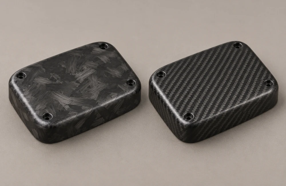
What “forged carbon” means in manufacturing
In common composite usage, forged carbon describes chopped carbon strands consolidated with resin in a mold under pressure. The word does not mean that carbon fibers undergo the metal-forging process. Fiber length, bundle size, resin, charge preparation and consolidation conditions can differ substantially between products sold under the same broad label.
Easy Composites’ compression-molding tutorial distinguishes chopped prepreg processed with heat and pressure from dry fiber with liquid resin. This illustrates why the term alone does not specify one curing cycle or one manufacturing setup.
Ask the supplier to identify the actual material form and route. A room-temperature demonstration with a particular resin should not be treated as instructions for an industrial molding compound. Likewise, a fast cycle advertised for a named commercial material does not establish the cycle time, quality or cost of an unrelated custom part.
Use specific language in the purchase specification: material designation, reinforcement form, resin system and agreed molding route. “Forged carbon appearance” may be an appropriate cosmetic request, but it leaves structural construction open unless the drawing or material specification defines it separately.
What woven carbon describes—and what it leaves open
Woven carbon reinforcement contains continuous yarns interlaced in a fabric. Plain, twill and other weave styles affect appearance and handling, while the complete laminate also depends on ply orientation, number of layers, resin and consolidation. A visible twill face does not reveal every layer beneath it.
Hexcel’s woven reinforcement overview links fabric selection to mechanical needs, appearance, drape and impregnation. Those are separate design variables: the most attractive weave for a product face is not automatically the best complete structural arrangement.
Continuous reinforcement is broader than woven cloth. Unidirectional material places most reinforcement in a selected direction, while other constructions distribute it differently. Hexcel’s unidirectional fabric information provides a distinct category. Avoid using “woven” as a synonym for every continuous-fiber laminate.
For a custom component, define whether the fabric is structural, cosmetic or both. If a woven outer layer covers a different core or internal construction, specify the whole assembly. Calling it simply “solid carbon” can leave the buyer and manufacturer with incompatible expectations about weight, section and load carrying.
Compare complete constructions, not pattern names
| Decision | Chopped-fiber molded route | Woven or continuous-fiber route |
|---|---|---|
| Reinforcement | Discontinuous strands or bundles with a specified distribution | Continuous yarns or plies with defined orientation |
| Geometry | Review charge flow, cavity filling and local thickness | Review drape, ply placement, corners and consolidation |
| Load path | Assess local orientation and component-level behavior | Design the layup around relevant load directions |
| Appearance | Agree an acceptable range of irregular bundle patterns | Agree weave type, alignment and permitted distortion |
| Economics | Consider mold, press route, charge preparation and finishing | Consider tooling, cutting, layup, consolidation and finishing |
| Acceptance | Check dimensions, internal quality and required performance | Check dimensions, laminate quality and required performance |
This table is a review framework, not a ranking. A thick chopped-fiber molding and a thin woven laminate are not directly comparable merely because both contain carbon. Their mass, stiffness, failure modes and production effort may differ because the designs solve different problems.
Define the comparison basis before requesting quotations. Equal outside dimensions may be useful for a packaging constraint, while equal stiffness or equal mass may be the relevant engineering target elsewhere. State which variables may change so that suppliers can propose meaningful alternatives rather than quote visually similar but functionally unequal parts.
A practical sequence for narrowing the options
First, separate constraints from adjustable features. The available space, interface locations and required service conditions may be fixed, while wall thickness, local ribs or an internal construction may be open to change. Tell the supplier which features are genuinely fixed and why. Otherwise, a useful manufacturing proposal may be rejected simply because it differs from an early concept model.
Second, decide whether appearance or structural performance is driving the selection. A decorative insert still needs secure retention and adequate durability, but it does not necessarily require the same evidence as a load-bearing bracket. Identify the consequences of failure and the expected duty. This gives the engineering team a basis for choosing an appropriate level of analysis and testing.
Third, ask for a manufacturing explanation for each candidate. The explanation should connect the material form to how the shape is produced, how critical surfaces are finished and how the result is checked. It need not disclose confidential process details to be useful. It must, however, be specific enough to show that the quotation covers the actual component rather than a generic carbon-fiber capability.
Fourth, define the first sample’s purpose. A visual sample can establish pattern and gloss; a dimensional sample can establish fit; a functional sample may be needed for load or exposure testing. One sample may serve several purposes, provided its construction and processing are representative. A cheaper appearance mockup should not silently become the basis for structural approval.
Finally, record why the selected route meets the requirements and what remains conditional. For example, a route may be preferred because it accommodates the required shape, while final approval still depends on a mounting-point test. Keeping that condition explicit helps purchasing, engineering and the manufacturing partner work from the same decision rather than different interpretations of a verbal preference.
The result is a short, reviewable selection record: required function, proposed construction, permitted geometry changes, evidence reviewed and outstanding checks. This record is more useful for repeat orders than a statement that one carbon style is generally superior. It also makes a later material substitution easier to evaluate because the original reasons remain visible.
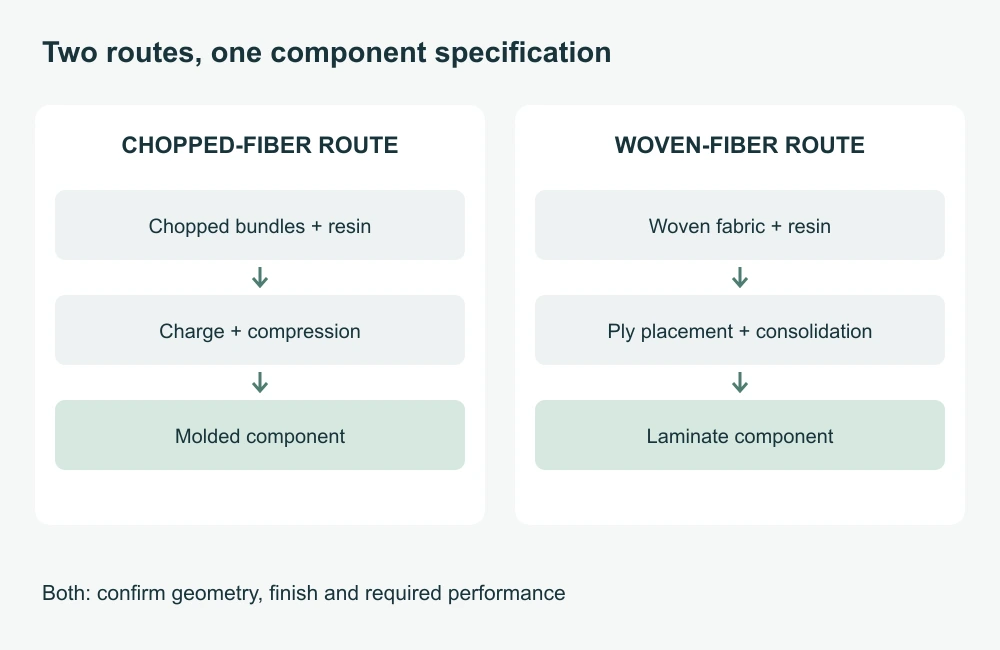
Start structural selection with loads and orientation
Identify the directions and types of load: tension, compression, bending, torsion, local bearing and repeated loading. Also define supports and connections. A component can be strong in one test and unsuitable for another duty, so the request “make the stronger carbon version” needs a more precise engineering target.
Continuous reinforcement can be arranged to follow important load directions, but the final response depends on the full layup and geometry. A woven face alone does not establish that arrangement. Thickness, ply orientation and local details should come from the structural design, not from an assumption that a familiar checker pattern guarantees strength.
Chopped-fiber material is sometimes described as having random orientation. That does not justify treating every molded region as perfectly isotropic. An original study of a compression-molded ribbed structure compares fiber-orientation predictions with computed tomography, illustrating why actual flow and geometry need attention.
For a load-bearing part, ask what evidence represents the critical region. A flat coupon may support material characterization without reproducing a rib junction, hole, thick transition or insert. Use analysis and appropriate component testing where required, and identify the design authority responsible for accepting the load case.
Keep stiffness and strength separate. A part may survive a load but deflect too much for alignment or appearance. Conversely, a sufficiently stiff part can still have a local failure concern at a connection. State allowable movement and relevant failure criteria rather than relying on one headline tensile-strength number.
Let geometry guide the manufacturing review
Chopped-fiber compression molding can be considered for three-dimensional shapes with local changes in section. Hexcel describes HexMC molding material for complex shapes and thickness transitions. This is evidence for a named material family, not a promise that any forged-carbon recipe can reproduce every detail.
Discuss ribs, bosses, corners and flow restrictions with the molder. The cavity must fill and consolidate using the selected charge and process. A narrow feature that looks straightforward in CAD may demand a different material distribution, tool design or geometry. The finished surface cannot reveal whether that development has been completed.
For woven laminates, examine how fabric follows curves and corners. The intended pattern and reinforcement placement must coexist with drape and consolidation. A cosmetically strict alignment requirement on a compound curve may increase the difficulty of layup or require a different surface design.
Identify which faces are mold-controlled and which will be trimmed or machined. That distinction affects dimensions, appearance and the number of operations. A design with several close-fitting interfaces may still need secondary machining even when the broad shape is molded accurately.
Review draft, parting lines, release and access before treating the model as manufacturing-ready. These issues are relevant to the selected tooling route, not evidence that one architecture is inherently poor. A small geometry adjustment can preserve function while making demolding, trimming or inspection more practical.
Specify tooling and production route together
The tooling must suit the pressure, temperature, resin and required life of the selected process. A mold used successfully for a low-temperature development demonstration may be unsuitable for another compound. Obtain the material supplier’s processing guidance and the molder’s proposed route before choosing tooling solely on initial cost.
The HexMC user guide gives material-specific instructions, including metallic tooling for its compression process. Its requirements illustrate the need to distinguish named industrial compounds from other chopped-fiber methods; they should not be generalized into universal settings.
For a woven part, identify whether the proposal uses prepreg, infusion, another resin-transfer route or a different agreed method. “Woven carbon” does not imply an autoclave, and the absence of an autoclave alone does not establish poor quality. The relevant question is whether the actual route achieves the defined laminate and acceptance requirements.
Separate prototype tooling from production tooling in the proposal. State which decisions the prototype is intended to validate and which remain open for the production route. A prototype can demonstrate fit or appearance while providing incomplete evidence of repeatability under a different mold and process.
Agree ownership, maintenance and revision control of dedicated tooling where commercially relevant. If the part geometry changes, assess tool changes and the need for renewed samples. Tooling is part of the reproducible manufacturing definition, not simply a one-time charge disconnected from the accepted product.
Review charge placement, layup and internal quality
For a chopped-fiber route, the manufacturing plan needs a controlled charge: its amount, distribution and preparation must suit the cavity and material. A marbled surface does not show whether the interior has the intended reinforcement distribution or consolidation. Define the process records and quality evidence appropriate to the application.
For a woven route, control fabric identification, ply sequence, orientation and placement. Wrinkles, bridging or unintended gaps require assessment against the part’s requirements. A visually straight outer weave does not establish that the internal layers were placed correctly.
Both routes need a way to address voids, incomplete consolidation and other relevant internal conditions. The appropriate inspection depends on material, thickness, geometry and risk. Avoid promising that a generic visual inspection will find every internal defect or that one method works equally well on every construction.
Ask how nonconforming material is identified and dispositioned. Filling a surface pore or polishing a blemish may change appearance without answering an underlying structural question. Cosmetic repair, dimensional rework and structural repair should have distinct approval criteria.
Keep process identity through trimming, coating and assembly. Once several visually similar samples are mixed, it may be impossible to connect an attractive piece to the route that produced it. Sample identification should remain readable outside the evaluated surface and link to the relevant material and process record.
Resin and service environment belong in the comparison
The reinforcement label does not define heat resistance, chemical compatibility, moisture response or surface durability. Identify the resin system and the relevant cured condition, then review the intended environment. A carbon-fiber component can retain its visible pattern while another part of the composite system no longer meets its requirement.
Specify exposure rather than vague descriptions such as “outdoor grade.” Temperature range, contact with fluids, cleaning products, humidity, sunlight and load during exposure can affect the review. A supplier needs enough detail to identify relevant evidence and propose a suitable material and finish.
Do not treat a quoted glass-transition temperature as a universal continuous-use temperature. Its method, cure state and conditioning matter, and the component’s mechanical requirement may impose a different limit. Ask the material supplier or responsible engineer to connect the data to the actual application.
If a clear coat is required, include it in appearance and environmental validation. The coating can influence gloss, color and handling behavior without changing the underlying reinforcement architecture. Confirm compatibility with later bonding, marking or repair rather than adding the coating after the main design is approved.
Approve pattern, gloss and variation explicitly
Forged-carbon appearances generally show irregular bundles, while woven appearances show an organized textile pattern. Actual visual results depend on surface preparation, molding, coating and lighting. A photograph may communicate the design direction, but a physical sample provides a better basis for the acceptable finish.
For chopped-fiber patterns, agree how much variation is expected between parts. A customer seeking identical placement of every visible bundle is requesting something different from an irregular material pattern. Identify unacceptable resin-rich-looking areas or blemishes through agreed examples without assuming that appearance alone diagnoses their internal cause.
For woven surfaces, define weave style, visible orientation and alignment between neighboring pieces. Clarify how the pattern may change around curves or at trimmed edges. A requirement for continuous visual alignment across separate molded components can affect tooling, layup and rejection rates.
Approve gloss and texture separately from architecture. Matte, satin and polished surfaces change perceived contrast, but they do not identify fiber continuity or prove strength. Keep the accepted sample linked to its finish specification so that a later coating change does not silently change the product appearance.
Use controlled viewing conditions for side-by-side approval. If instrumental measurement is needed, agree a method suitable for the geometry. Distinguish a preferred target from an acceptance-limit sample; an attractive showroom piece should not become an undefined promise that every natural pattern will be identical.
Include machining and finishing in the original design
Molding can establish much of the shape while leaving holes, edges or fitting surfaces for later work. Identify these operations before approving the material route. Tool access, support and inspection may influence the design of a boss, an opening or a narrow decorative insert.
Machining continuous-fiber laminates cuts across an arranged reinforcement structure. Machining chopped-fiber moldings encounters a different local architecture. Both require suitable tools and damage criteria, but the same process cannot be assumed from a shared carbon-fiber label.
Define final dimensions after all relevant finishing operations. A clear coat, polishing allowance or edge treatment can matter at a close fit. Keep cosmetic areas distinct from bonding and locating surfaces so that a finishing step does not remove a required feature or contaminate an interface.
Review how exposed edges should appear and be handled. The acceptable edge of a hidden mounting plate may differ from one touched by the end user. Any sealing or finishing requirement should be specified for the actual resin and service conditions, rather than treated as an automatic universal operation.
Connections can determine which route is practical
Loads often enter through fasteners, inserts or adhesive joints. Describe those interfaces early because they can control local geometry and reinforcement requirements. Choosing a carbon pattern first and designing the attachment later can create a part that looks appropriate but is difficult to assemble reliably.
For fasteners, review bearing area, edge distance, local section and installation method with the design authority. For inserts, specify how they are retained and whether they are molded in or installed later. A molded boss is not automatically ready to accept any thread or installation force.
For bonded assemblies, identify the adherends, preparation, adhesive and cure requirements. Surface appearance approval does not prove bondability. Mold release residue or a decorative finish can be relevant to the joint, so the bonding surfaces need their own controlled condition.
For carbon-metal combinations, assess environmental exposure and any required isolation along with mechanical behavior. Neither woven nor forged-carbon appearance resolves that issue. The complete joint must be reviewed as a system rather than accepted from separate material brochures.
Validate the decision on representative samples
Write the decision questions before ordering samples. Separate fit, appearance, mass, stiffness, strength and environmental performance. A sample can resolve one question while leaving another open, and the approval record should show that distinction clearly.
Compare alternatives on a defined basis. If the objective is lower mass at adequate stiffness, record both mass and the relevant displacement under stated conditions. If the objective is appearance on an existing shape, keep the geometry and viewing conditions comparable. A test only becomes meaningful when its conditions match the decision.
Material coupons can support characterization, but they do not automatically represent a finished component with holes, ribs, inserts or thickness changes. Decide which requirements need component-level evidence and who evaluates it. Do not claim that a photographed sample has passed a test that was never commissioned.
Example: choosing a construction for an instrument cover
Consider a hypothetical cover with a curved outside face, a shallow internal recess and several mounting points. The customer wants a carbon appearance, a defined maximum mass and enough stiffness to keep a seal interface aligned. The first step is to identify whether the cover carries substantial loads or mainly provides enclosure and appearance.
For a woven proposal, ask how the fabric will follow the curvature, where the layup changes and which face controls the visual pattern. For a chopped-fiber proposal, ask how the molding charge reaches the local features and how the mounting regions are defined. In both cases, the final dimensions and seal interface remain explicit acceptance requirements.
Request representative samples with traceable construction and finish. Measure the agreed features, review the visible surface and conduct the relevant stiffness or assembly check. A lighter sample that fails alignment is not automatically the better solution; a heavier sample may also be unacceptable if the mass limit is essential.
If one route requires a small geometry change, compare that revised component against the actual requirements rather than insisting on a shape optimized for the other route. Record the change, the resulting benefit and any new uncertainty. The purpose is to choose a manufacturable design, not to force two architectures into an artificial identical recipe.
Keep the sample approval scoped to what was demonstrated. A fit-and-appearance approval should remain labeled as such until the required functional evidence is available. If the production supplier, resin or construction changes, review the affected evidence before treating the new part as equivalent.
Read comparison data without mixing unlike tests
Check specimen geometry, fiber content definition, orientation, conditioning and test method before comparing a property table. Fiber mass fraction and fiber volume fraction are different quantities. Tensile strength, flexural strength and stiffness answer different questions and should not be combined into a single unsupported “strength score.”
Easy Composites’ mechanical comparison is an example of testing defined constructions rather than judging by pattern. Its results belong to its specimens and methods; they are not universal values for every forged-carbon or woven product.
Separate typical data from design allowables and contractual minimums. A published average may help screen candidates without guaranteeing every delivered component. The responsible engineer must determine how evidence, variation and the intended consequence of failure affect the final requirement.
Compare total cost and the repeat-order specification
There is no fixed price ranking between forged and woven carbon without geometry, quantity and quality scope. Tooling, charge preparation or layup labor, cycle, yield, secondary machining, finish and inspection all contribute. A lower molding price may omit operations included in another quotation.
Separate development and tooling from recurring part cost. Ask which sample iterations are included and what triggers a new charge. For a small order, tooling and development can dominate; for repeated production, consistency and accepted yield may become more important. Compare the same commercial scope.
Define the repeat-order package: material designation, construction, drawing revision, approved process basis, finish, reference sample and inspection plan. Preserve the supplier’s agreed responsibilities. A repeat order described only as “the same forged look” can reproduce a pattern while changing the actual component.
Do not claim recycled content, zero waste or a lower environmental footprint from the visual texture. Chopped fibers can come from different feedstocks, and overall impact depends on the actual supply chain and process. Any such claim needs evidence specific to the supplied material and order.
Frequently asked questions about forged and woven carbon
Is forged carbon stronger than woven carbon?
Not as a universal rule. Compare complete constructions under relevant loads, including geometry, resin, orientation and quality. A result from one test does not rank all possible components.
Is woven carbon always lighter?
No. Finished mass depends on geometry, reinforcement and resin content, core, inserts and coating. State the required mass or weight target for the actual part and verify the proposed construction.
Can a woven surface cover a different internal structure?
Yes. The visible layer does not establish the complete build. Specify whether the surface is decorative, structural or both, and confirm the remaining construction.
Does forged carbon mean recycled carbon?
No. The appearance and process label do not establish feedstock origin. Request traceable information if recycled content is part of the requirement.
Discuss both carbon options with KeepWin
KeepWin offers project discussions for forged or chopped-fiber and woven or continuous-fiber carbon-composite options. The KW-6502 carbon-and-titanium design reference and corresponding Samsung design reference provide product starting points. Their galleries do not prove that both internal constructions are pictured.
For watch-band components or other custom parts, identify the geometry, quantity, load or assembly function, appearance and inspection needs. Construction, sample and price are confirmed for the order. Use the drawing preparation guide to organize the brief, then submit a parts manufacturing inquiry.
KeepWin coordinates requirements with suitable manufacturing partners; the written proposal defines the actual material, processing and inspection scope. The decision should finish with an approved component specification, not simply a choice between two photographs.