
Enclosure and cover
Show closure, seam, fastening and service access. Identify the final assembled reference and any separately specified protection requirement.
APPLICATION REVIEW / ELECTRONICS MECHANICAL PARTS
A housing may need to locate a board, expose a connector, retain a cover and meet a visible finish reference. Define those relationships before using a process name or render as the production specification.
KeepWin coordinates partner-supported review. Exact material, responsible operations, process availability, dimensions, inspection, commercial quantities and timing are confirmed in the project proposal; no universal capability or certification is promised.
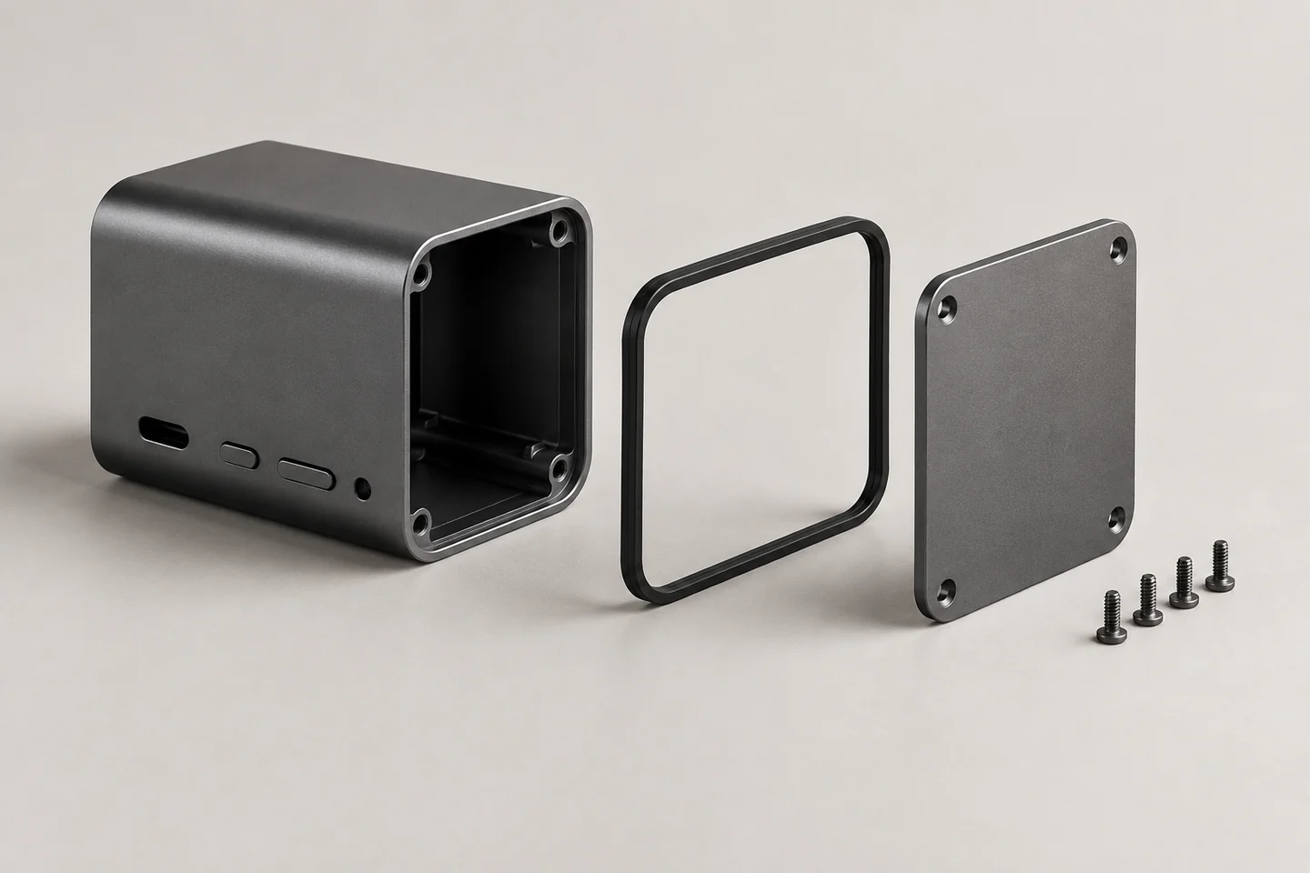
Generated electronics enclosure concept. No working electronics, ingress protection, shielding or regulatory performance is demonstrated.
01 / PART SCOPE
Enclosures, mounts and user controls have different checks. Define the supplied scope so a housing sample is not mistaken for an approved electronic product.
Show closure, seam, fastening and service access. Identify the final assembled reference and any separately specified protection requirement.
Provide board, module or accessory locating references. Mark mounting relationships and permitted contact or clearance.
Define motion, retention, tactile intent and visible surfaces. Appearance or fit samples cover only the agreed questions.
02 / ASSEMBLY INTERFACES
Board thickness, connectors, covers and inserts can combine into a fit problem that loose-part dimensions do not reveal. Supply mating references and the accepted state.
Show the actual mating connector or cable reference and the assembly relationship. Define edge condition and finish effects on the opening.
Specify engagement purpose, access and component identity. Review retention or repeated-use requirements with an agreed test scope where needed.
Identify locating datums, closure path and permissible appearance. Any sealing-related requirement needs a defined configuration, method and criterion.
Map grounding, bonding or contact areas if relevant. Conductive appearance is not proof of electrical performance; responsible application evaluation remains explicit.
03 / ROUTE SELECTION
Geometry, sample purpose and repeat volumes can lead to different preparation. Include finish and assembly work when comparing offers.
| Route | Review priority | Sample limitation |
|---|---|---|
| Machined enclosure | Tool access, pockets, fastening and final finish. | A measured sample covers its stated configuration. |
| Molded housing | Wall/rib relationships, tooling and inserts. | Prototype material may not represent molded delivery. |
| Sheet enclosure | Bends, seams, hardware and coating. | Flat profiles do not verify the finished assembly. |
| Printed development | Assembly access and shape iteration. | No universal thermal, electrical or use approval. |
04 / COSMETIC CONTROL
Lighting, texture and substrate change the appearance. A screen color or concept image alone is insufficient for accepting a finished housing.
Identify visible, hidden and contact faces. Define permitted process traces, seams and marks for each relevant area.
Supply a physical color/texture reference where needed. Agree viewing conditions and the finish state of the comparison.
Review substrate, treatment, masking and assembly order. Confirm any effect on port, seam and fastener interfaces.
Identify surfaces that can rub or mark in transit. Agree protective scope rather than assuming generic packing preserves every finish.
05 / ACCEPTANCE SCOPE
A fit check or material record does not certify the complete device. Define who owns electrical, thermal, environmental and regulatory evaluation.
| Question | Define | Evidence boundary |
|---|---|---|
| Assembly fit | Mating references, method and final state. | Specified components and sample scope. |
| Appearance | Faces, physical reference and viewing basis. | Agreed finish and comparison conditions. |
| Material | Exact specification and relevant documentation. | Supply identity, not whole-device approval. |
| Application | Required test and criteria. | Responsible configuration and evaluator. |
06 / QUOTATION BRIEF
The lowest bare-part price may exclude the work needed to achieve the finished interface. Ask for scope items that affect acceptance.
Provide CAD/drawings, board/connector and cover references, exact material, critical interfaces, finish map and variants. State quantity and destination.
Identify preparation, tooling where relevant, manufacture, inserts/hardware, finish, assembly checks, records and packing.
Agree sample questions and ownership of product-level evaluation. Exact process availability, numerical limits, minimum quantities and timing are confirmed per proposal.
07 / QUESTIONS
Provide the enclosure relationship and the scope of application evidence.
No. It illustrates a mechanical concept and does not demonstrate electronics, protection or compliance.
No universal performance is claimed. Define contacts, assembled configuration and the required evaluation.
Only its represented questions. Material, tooling and final-state differences need review before extending approval.
Identify the substrate, process and physical reference with agreed viewing conditions. Screen appearance alone is insufficient.
Only the explicitly agreed scope. List required secondary work and final acceptance in the enquiry.
PREPARE THE NEXT DECISION
Include controlled enclosure and mating-part files, board/connector references, exact materials, fastening intent, cosmetic areas, application checks, quantities and destination.
sales@keepwinco.comAn enquiry starts a team review. Material, fit, quantity, schedule, operation responsibility and supporting records are confirmed in the proposal; this form does not create an order or an instant price.
Start with what you know. Review your details before sending; no account needed.
Start parts inquiry →Your project is saved securely only when submission succeeds.