
November 15, 2026
Why Is Titanium Difficult to Machine? Challenges and Design Considerations
Titanium is difficult to machine because heat concentrates near the cutting edge, the material can react with the tool, and relatively flexible parts can move away from the cut. A successful process controls those effects together. Simply slowing the spindle, choosing a harder coating or clamping the part more tightly does not address every cause.
A small sculpted watch-band link illustrates the problem: several holes, curved show faces and narrow connecting sections can make a compact part demanding. The same questions apply to brackets, instrument housings and other custom components. A finished product photograph reveals the geometry, but not the stock condition, fixtures or cutting sequence used to manufacture it.
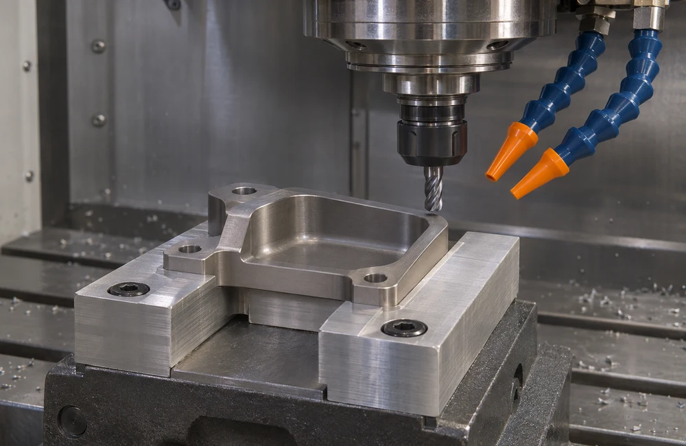
What makes titanium machining demanding?
The practical challenge is maintaining a stable cutting edge while the stiffness of the tool and workpiece changes around the component. Titanium is not a single machinability category: commercially pure grades, alloy grades, heat treatments, stock forms and surface conditions can require different approaches. Establish these before comparing cycle times or choosing cutting data.
A useful first review separates three questions. Is the cutting edge operating under suitable thermal and mechanical conditions? Can the part and fixture resist the applied forces without unacceptable movement? Does the finished component satisfy its requirements after it leaves the fixture and receives its final surface treatment? Passing one of these checks does not prove the others.
| Observation | Possible contributors | First useful check |
|---|---|---|
| Rapid edge deterioration | Heat, adhesion, unsuitable engagement or tool condition | Compare edge condition and cutting history |
| Wavy or inconsistent walls | Tool deflection, workpiece motion, vibration | Relate the marks to tool reach and local support |
| Dimensions change after unclamping | Elastic clamping distortion or stress redistribution | Compare defined clamped and free-state measurements |
| Damaged holes or burrs | Tool wear, evacuation, breakthrough conditions | Inspect entrance, bore and exit separately |
This table is a diagnostic starting point, not a way to identify a root cause from a photograph. Several mechanisms can produce similar marks, and more than one may be present on the same component.
Heat, adhesion and elastic movement are different problems
TIMET identifies low thermal conductivity, interaction between titanium and cutting tools, and the material’s comparatively low elastic modulus as machining considerations. Heat concentrated near the edge can shorten its useful life; pickup can alter the effective cutting geometry; elastic movement can change the actual material removed. These mechanisms help explain why a titanium operation needs its own process review. TIMET’s design and fabrication handbook provides the underlying material guidance.
For a production investigation, turn those mechanisms into separate observations. Record whether an edge wears progressively or breaks suddenly. Check whether dimensional drift follows the number of parts, appears at one toolpath location, or starts only after a setup change. Record whether the error is visible while clamped or emerges on release. The resulting pattern is more useful than the description “titanium is hard.”
Do not use chip color alone to determine the temperature of a finished surface or to certify its integrity. Likewise, a smooth-looking wall does not establish that its dimensions are correct. Appearance, geometry and material condition answer different acceptance questions. If a component has a critical fatigue or surface-integrity requirement, the drawing and verification plan need to address that requirement explicitly.
A sensible investigation changes one controlled factor at a time when practical and records the complete setup. Otherwise, replacing a cutter, moving a coolant nozzle and changing the fixture together may improve the result without explaining which change mattered. That uncertainty becomes expensive when the same problem returns later.
Confirm the grade and stock condition before choosing parameters
KeepWin’s titanium designs can be discussed in Grade 2 commercially pure titanium or Grade 5 Ti-6Al-4V. These are distinct material options, not interchangeable names. The selected grade must cover the intended components, and associated hardware may require its own specification. Our Grade 2 versus Grade 5 selection guide addresses that material decision separately.
For machining, identify the supplied stock as well: product form, condition, specification and any relevant surface allowance. A drawing that says only “titanium” leaves important purchasing and process assumptions unresolved. A bar, plate or near-net-shape blank can require different reference surfaces and material-removal plans even when the nominal alloy designation matches.
Separate mandatory requirements from alternatives that the design owner may approve. If a supplier proposes another stock form to reduce machining, compare the effect on material documentation, orientation requirements, dimensions and inspection. A cheaper blank is useful only if it can support the required finished component and the approval is recorded before production.
When comparing samples, use the same agreed material basis. A change of grade alongside a new fixture or toolpath makes the comparison difficult to interpret. Keep material identity, drawing revision and process trial records connected so that a successful sample can be traced to the conditions that produced it.
Select a tool system, not a coating name
The cutting tool includes its substrate, edge preparation, geometry, coating where applicable, holder and reach. These choices interact. A tool that fits the nominal pocket diameter may still have insufficient neck clearance, excessive overhang or poor access to the last finishing surface. Check the complete tool envelope against the workpiece and fixture.
Kennametal explains that coating selection depends on the workpiece material, application, geometry, feed, speed and coolant use. That is a useful reason to avoid specifying a coating solely because it is advertised as hard or heat resistant. Ask the tool supplier for a recommendation tied to the actual titanium grade and operation. Its guide to carbide end-mill grades and coatings explains that selection framework.
At the design stage, preserve space for a suitably stiff tool. If a narrow, deep feature forces a long small-diameter cutter, discuss whether the feature can be widened, shortened, opened from another direction or divided into separate components. These are design alternatives for approval, not permission for a manufacturer to change a drawing unilaterally.
Document a replacement criterion before running a batch. It may combine observed edge condition, dimensional trend and surface acceptance. Waiting for complete tool failure can turn a manageable maintenance decision into a damaged part. Conversely, replacing tools without recording their condition gives little evidence for improving the process.
Why engagement and chip thickness matter
A cutter’s load depends on where and how it contacts the material. A toolpath that is stable along a straight wall can become demanding when it enters a tight corner or an area with uneven remaining stock. Review those transitions instead of treating the programmed feed rate as a complete description of the cut.
Kennametal’s titanium milling guidance discusses radial engagement, dynamic paths, coolant delivery and tool-wear monitoring. The transferable principle is to coordinate the path and cutting conditions; its examples are not universal settings for every part or machine. Read the manufacturer’s titanium milling guidance when discussing a specific tooling proposal.
“Use a lighter cut” is incomplete advice. The machining team must consider chip thickness, edge geometry, engagement and machine behavior together. A reduction that produces rubbing rather than effective cutting may create another problem. Ask for the proposed operating window and the observations that will justify changing it during the trial.
For a buyer reviewing cost, ask which features interrupt an otherwise efficient path. A deep corner, a narrow connecting web or an isolated boss may control a disproportionate share of the cycle. Removing unnecessary restrictions from one feature can be more useful than requesting a small percentage reduction in the overall machining price.
Any approved geometry change should appear in the model and drawing together. Leaving an old drawing beside an updated model invites conflicting interpretations during programming, inspection and subsequent repeat orders.
Treat coolant delivery and chip removal as part of the process
Coolant planning includes the tool’s requirements, delivery to the active cut, access through the fixture, and removal of chips. The existence of a coolant system on the machine does not establish that fluid reaches a deep feature throughout the operation. A nozzle position that works at the top of a pocket may become ineffective as the cutter moves.
ISCAR’s titanium machining reference discusses the relationship between tooling, coolant and application conditions. Use the relevant tool manufacturer’s instructions to determine the appropriate delivery method and operating limits. A pressure value taken from another tool or machine is not a complete process specification. ISCAR’s reference guide offers operation-specific context.
During a review, ask how chips leave blind pockets and drilled features, whether fixtures obstruct the route, and how the operator recognizes a loss of effective evacuation. Also define how coolant condition will be maintained under the fluid supplier’s instructions. Fluid compatibility with later cleaning, bonding or coating should be considered before the complete route is approved.
Keep shop safety separate from productivity claims. Titanium chips and fines require an appropriate collection, housekeeping and fire-response assessment for the actual operation. This article does not prescribe an extinguishing method or a substitute for the facility’s safety procedures. The component drawing should not force unsafe handling simply to protect a cosmetic face.
Workholding must support the cut without distorting the part
A fixture needs to establish location, resist the machining forces and release the component without leaving an unacceptable permanent or elastic shape change. Increasing clamp force is therefore not a universal remedy for vibration. A slender component can be held securely while also being bent away from the shape that inspection expects.
Mark the intended datum surfaces and ask which regions contact the fixture in each setup. Distinguish locating contacts from clamps and supporting contacts. A contact near the cutting zone may improve local support, but it must not obstruct the tool or introduce a conflicting location constraint. The arrangement needs review as a system.
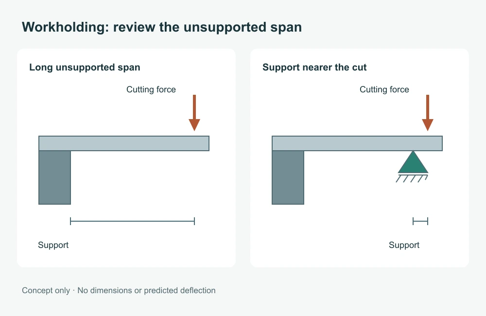
For a hypothetical pocketed bracket, a proposed process might retain a supporting base while internal features are machined, then transfer to a fixture that references stable finished surfaces. This describes a planning option, not the route used for a specific KeepWin product. Its suitability depends on the geometry, allowed witness marks, remaining stock and measurement access.
Require a defined free-state check when the drawing’s function depends on the unloaded shape. If the component is meant to be measured in an assembled or restrained condition, state that condition instead. An inspector cannot fairly compare a clamped reading with an unloaded tolerance without knowing which state the specification requires.
Plan roughing, finishing and datum transfer together
Roughing removes most of the stock; finishing establishes the required surfaces. Their relationship matters because each material-removal stage changes the remaining geometry and support. A plan should explain which reference surfaces survive between setups and how the next setup finds them. “Finish everything last” does not answer that question.
Review stock allowance around critical surfaces. Uneven allowance can change the final cutter load, while insufficient allowance may leave no opportunity to remove earlier marks. The appropriate allowance is a process decision supported by trials and the actual stock condition, rather than a universal number to copy into every titanium drawing.
Where thin regions or asymmetric removal create concern, discuss intermediate checks and the condition in which they will be performed. If a thermal or stress-relief operation is proposed, obtain approval against the material specification and final properties; do not add a heat treatment merely because distortion is present. It may change more than the shape.
Include later deburring and surface treatment in the sequence review. A dimension measured before polishing or coating may not represent the delivered interface. Identify which checks occur before finishing to diagnose the machining process and which must occur afterward to accept the finished component.
The objective is an observable sequence: a technician should be able to identify the current datum, the remaining allowance and the acceptance point at each important handoff.
Small holes and threads need their own review
Holes can combine restricted coolant access, chip evacuation, breakthrough burrs and difficult inspection. Identify diameter, depth, entry geometry, intersections and whether the hole breaks through. A short through-hole and a deep blind hole should not be treated as equivalent simply because their nominal diameters match.
Distinguish a clearance hole from a locating or bearing feature. Specify the functional requirement and let the proposed manufacturing plan explain how it will be achieved. Drilling, subsequent sizing and inspection may be different operations. The drawing should not require a particular route unless that route is itself necessary to the design.
For threads, define designation, required engagement, entry condition and available tool access. Tapping and thread milling each have application constraints; choosing between them requires the real diameter, depth, material and machine context. A claim that one is always better for titanium overlooks those constraints and the cost of verification.
Plan access for deburring intersections without damaging adjacent faces. “Burr free” still leaves questions about allowed edge break, accessible inspection and protected surfaces. Put those requirements on the drawing or agreed inspection instruction. If a small interface is critical, consider a functional check alongside dimensional inspection, while preserving the distinction between the two kinds of evidence.
Separate machining finish, edge condition and final appearance
Surface roughness, visible tool marks, gloss and edge geometry are related but different characteristics. A cosmetic reference does not define a roughness measurement, and a roughness value does not guarantee an acceptable visual match across adjacent parts. State the requirement for each relevant face instead of applying one vague “smooth finish” note everywhere.
Identify show faces, mating faces and hidden surfaces. A contoured link such as the KW-4036 design is useful for discussing visible transitions and small interfaces. Its photograph is not evidence of a particular cutting strategy or coating process. For a custom enclosure, the same distinction separates an exterior appearance requirement from a gasket or locating surface.
Agree how edges will be treated without changing the intended function. An unrestricted polishing instruction can conflict with a controlled corner or fit. Conversely, an excessively sharp edge requirement can be inappropriate for a handled component. Identify the function and acceptable edge condition before deciding how to achieve it.
Use a physical appearance reference when needed, together with defined viewing conditions. Keep dimensional acceptance independent of whether a sample looks attractive. Our surface-finish reference guide explains how to record appearance requirements without confusing photographs with manufacturing specifications.
Inspect in a state that represents the requirement
A useful inspection plan defines the characteristic, datum, measurement method, part condition and acceptance decision. A report containing many dimensions can still miss the critical question if the component was measured under an inappropriate restraint or before the final operation that changes the interface.
For a thin feature, record how the part is supported and avoid making the inspection fixture reproduce the machining distortion. Allow the component and measuring system to reach the agreed measurement conditions. Where thermal effects or contact force are significant relative to the tolerance, include them in the method assessment rather than assuming every reading is directly comparable.
Use measurement uncertainty and repeatability appropriate to the decision. A caliper reading may help locate a large process shift without being suitable for accepting a tight feature. Optical, tactile or functional methods also have limits. Select a method because it can resolve the requirement with suitable confidence, not because its equipment name sounds impressive.
Record results across the intended tool-life interval when stability is the concern. One successful first piece does not establish that the final piece before a tool change will match it. Conversely, a late failure does not automatically invalidate an entire batch; containment and disposition should follow traceable records and the agreed quality procedure.
Make the trial answer a specific question
Before sampling, write down the uncertainty being tested. For example, the question might be whether a thin wall meets its form requirement after release, rather than whether the machine can produce an attractive prototype. Name the drawing characteristic, the measurement state and the evidence needed to reach a decision. A sample can then succeed or fail against an agreed purpose.
Keep a simple trial sheet with the material lot reference, tool identification, fixture version, program revision, relevant operating conditions and inspection results. The sheet does not need to disclose every commercial detail to every participant, but the responsible manufacturing team should retain enough information to reproduce the accepted condition. Photographs can document orientation and visible features; they should accompany, rather than replace, the measurements.
If two alternatives are compared, define what remains constant. Changing the tool and the wall geometry together can show that the new combination works, but it cannot isolate the effect of either change. That may be sufficient for a practical project decision, provided the conclusion is stated honestly. Do not describe it as a controlled proof that one cutter or one material is universally superior.
Also define the action after an inconclusive trial. Possible next steps include reviewing the measurement method, testing another supported geometry or returning to the design owner with an explicit tradeoff. Repeating the same operation without recording why it should behave differently is unlikely to resolve uncertainty efficiently. Retain the failed sample when its shape or surface provides useful evidence.
For production release, confirm what the sample approval actually covers. It may approve appearance while leaving a dimensional issue open, or approve one material and finish combination only. A signature on an unspecified sample is difficult to interpret later. Connect the approval to the part revision, the checked characteristics and any outstanding conditions before treating it as authorization for a repeat batch.
Finally, separate process development cost from routine unit cost. A trial fixture, special inspection arrangement or extra first-article measurement may be a one-time activity, while tooling consumption and finishing remain recurring. Clear separation helps the buyer evaluate whether a design change saves money over the intended quantity. It also avoids promising production economics on the basis of a single manually assisted prototype.
Troubleshoot the pattern, not just the visible defect
Begin with the last known acceptable condition. Check drawing revision, material identity, tooling, offsets, fixture condition and the measurement setup before attributing every deviation to titanium. A changed reference or damaged locating contact can imitate a cutting problem. Preserve the suspect tool and representative part where practical so that evidence is not lost.
| Pattern | What to compare | Avoid assuming |
|---|---|---|
| Gradual drift over successive parts | Tool condition, offsets, thermal state and measurement records | Every drift is tool wear |
| Repeated error at one corner | Engagement, remaining stock, access and local support | The entire program needs slower cutting |
| One setup differs from another | Datums, seating, clamping and transfer method | The material changed properties |
| Shape changes after release | Clamped and free-state form, removal sequence and restraint | More clamp force will solve it |
| Finish worsens after treatment | Pre-treatment records, masking and finishing allowance | The machining operation alone caused it |
Sandvik’s turning guidance distinguishes the effects of cutting speed, feed and depth of cut, including problems caused by values that are too low or too high. This supports investigating the actual failure mode instead of reducing every parameter together. Its recommendations are for turning and should not be copied directly into a milling operation. See Sandvik’s tool-life guidance.
Design changes that can reduce difficulty without changing function
Start with the feature’s job. A pocket may exist for clearance, weight reduction or assembly access; those purposes allow different compromises. When the function is clear, the machining team can propose a change that has a reason beyond being easier to cut. The design owner remains responsible for approving the resulting geometry.
Consider a hypothetical electronics bracket with a deep internal corner that does not locate another component. Increasing its radius may permit a more suitable cutter. If the corner provides clearance for a mating part, the same change may be unacceptable unless the assembly is adjusted. Review the assembly, not just the isolated machining model.
For a thin cover, ask whether local reinforcement or a different pocket arrangement can preserve the required envelope. For a small link, ask whether hole positions and cosmetic transitions require the same level of control. Neither example establishes a minimum wall thickness or tolerance that KeepWin promises; each opens a specific review question.
Prioritize changes by expected benefit and design impact. A proposal should name the affected feature, the manufacturing concern, the suggested change and the evidence needed for approval. The existing CNC milling design-review checklist helps organize this discussion without duplicating the material-specific analysis here.
Frequently asked questions about machining titanium
Does a stronger titanium grade automatically machine worse?
Strength matters, but it is not a complete machinability ranking. Grade, condition, operation, geometry, tooling and acceptance requirements interact. Compare the actual alternatives for the part. A material change also needs a design review; machining convenience alone does not establish suitability in service.
Should every titanium job run at the lowest possible speed?
No. Start from the tool manufacturer’s application guidance and validate the setup. A process must form and remove chips effectively while controlling heat and tool wear. “As slow as possible” is not an operating window and can conceal other causes of poor results.
Can better coolant compensate for a flexible fixture?
Coolant and mechanical support address different parts of the problem. Improved delivery may help the cutting conditions, but it cannot by itself establish accurate location or prevent an unsupported wall from moving. Evaluate the fixture, cutter reach and engagement as well.
Can a polished part be accepted without measuring it?
Only if the agreed specification genuinely has no dimensional or other functional acceptance requirement, which is unusual for mating components. An attractive surface does not prove hole location, free-state form or fit. Inspection must follow the actual requirements rather than appearance alone.
Turn the technical review into a workable project
For a titanium component, provide the exact material requirement, current model and drawing, quantity, critical interfaces, final surface condition and intended measurement state. Highlight unresolved questions instead of silently choosing assumptions. KeepWin’s CNC machining service coordinates requirements with specialist manufacturing partners; the written proposal defines the actual manufacturing and inspection scope.
Ask the response to identify the features driving difficulty and the decisions needed before sampling. Separate a proposed improvement from an approved drawing change. For a repeat order, preserve the agreed revision, material documentation requirements and sample reference so the discussion does not restart from an ambiguous photograph.
Send the project through the parts manufacturing inquiry page. The useful outcome is a clear plan for the actual part: how the material will be identified, how critical surfaces will be supported and machined, and how the finished result will be checked. The technical sources linked throughout this guide support general process understanding; they do not constitute records of a KeepWin production trial.