
Critical interfaces
Mark locating faces, hole relationships, mounting regions and assembled fit. Provide mating references rather than making every dimension equally critical.
PARTNER-SUPPORTED MANUFACTURING / DESIGN REVIEW
Make functional datums, feature locations and surface intent visible. A useful manufacturability review explains what can change and what the delivered assembly must retain, rather than publishing one rule for every stock and tool.
KeepWin coordinates partner-supported review. Exact material, responsible operations, process availability, dimensions, inspection, commercial quantities and timing are confirmed in the project proposal; no universal capability or certification is promised.
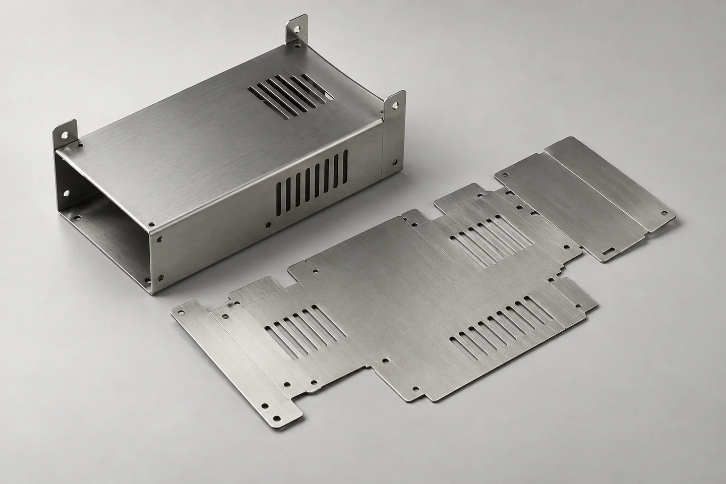
Generated sheet-part geometry reference. It does not establish sheet grade, thickness, measured dimensions or actual fabrication capacity.
01 / DESIGN PRIORITIES
Manufacturability changes can alter mating fit or appearance. Identify which features govern acceptance and which alternatives can be considered.
Mark locating faces, hole relationships, mounting regions and assembled fit. Provide mating references rather than making every dimension equally critical.
State where radius, relief, flange or feature changes are permitted. Require review of their effect on function and appearance.
Map surfaces controlling cosmetics, contact or finishing. Agree trace and edge limits relevant to the use.
02 / BENDS & ACCESS
Feature proximity, flange geometry and operation order can affect the formed result. No universal bend-radius or hole-distance value is asserted here.
Highlight holes, slots, notches and tabs near forming regions. Discuss likely shape effects and the final-state acceptance question.
Identify enclosed shapes, short or obstructed flanges and return features. Review access and sequencing for the responsible route.
Show where material must accommodate the bend or corner. Proposed relief changes should be approved against the interface and visible areas.
Specify required geometry or functional limits and acceptable alternatives. Confirm the offered tooling approach rather than assuming one radius for every material.
03 / FILE PREPARATION
Flattening assumptions belong in the reviewed route. Conflicting formed and flat files can hide different stock or bend definitions.
| Input | Include | Resolve |
|---|---|---|
| Formed model | Units, revision and final shape. | Controlling interfaces and proposed changes. |
| Drawing | Datums, fits, bend relationships and finish scope. | Requirement precedence. |
| Flat pattern | Revision and any controlling outline assumptions. | Consistency with the formed requirement. |
| Stock | Exact grade, thickness and condition. | Actual supply and route-specific preparation. |
04 / DESIGN DECISIONS
A simplified profile, relocated hole or new relief can answer a fabrication concern while changing the original assembly. Make the decision explicit.
Link each proposed modification to the relevant feature and purpose. Keep a controlled revision rather than accepting undocumented preparation edits.
State who can approve geometry, stock and surface changes. Define when mating or appearance review is required.
Consider how forming, joining or treatment changes the final relationship. Review the requirement at the delivered state.
Record stock, geometry and route represented by the sample. A changed design may require updated fit or dimensional evidence.
05 / ACCEPTANCE MAP
A flat blank dimension may not demonstrate a formed assembly relationship. Agree the reference, state and method before comparing results.
| Question | Check | Record |
|---|---|---|
| Mounting fit | Final positions and mating reference. | Datum basis and controlled revision. |
| Formed shape | Important flange and bend relationships. | State, method and sample scope. |
| Edges and reliefs | Functional edge and permitted geometry. | Accepted operation and reference. |
| Appearance | Visible-face traces and finish. | Physical sample and viewing conditions. |
06 / QUOTE REVIEW
A quotation can be more useful when it identifies open decisions and allowed alternatives. Required final geometry should remain clear.
Material/thickness, controlled files, critical interfaces, surface map, variants, quantity and destination. Mark what is mandatory and what may change.
Which geometry, stock, tooling or sequence changes are proposed? What is included for edges, secondary work, inspection and finishing?
Record accepted changes and their evidence before release. Numerical capabilities, MOQ, timing and records require confirmation for the actual proposal.
07 / QUESTIONS
State function and file precedence before applying a generic rule.
No universal value is provided. Review exact grade, thickness, geometry and the offered forming route.
Preparation assumptions need to preserve the controlling formed requirement. Approve changes that affect function or appearance.
They require review for the actual stock, geometry and tooling. Identify the final locating requirement rather than relying on one blanket rule.
It verifies only its agreed scope. Final datums and relationships should be checked after relevant operations.
Provide formed CAD, drawing and any relevant flat pattern, with units, revisions and governing-file precedence.
PREPARE THE NEXT DECISION
Include model and drawing revision, material/thickness, controlling dimensions, bend and relief intent, cosmetic faces, mating references, quantities and destination.
sales@keepwinco.comAn enquiry starts a team review. Material, fit, quantity, schedule, operation responsibility and supporting records are confirmed in the proposal; this form does not create an order or an instant price.
Start with what you know. Review your details before sending; no account needed.
Start parts inquiry →Your project is saved securely only when submission succeeds.
General material context only; external references do not certify a finished KeepWin product.
Protolabs - bend and flat-pattern context ↗Protolabs - sheet feature design context ↗