
Mounting brackets
Mark hole locations, contact faces and datums. Provide mating geometry so the final formed relationship can be checked meaningfully.
PARTNER-SUPPORTED MANUFACTURING / FORMED GEOMETRY
A bend moves more than an edge. Connect the radius, flange, nearby features and locating datums to the finished assembly, then review tool access and sequence for the actual stock.
KeepWin coordinates partner-supported review. Exact material, responsible operations, process availability, dimensions, inspection, commercial quantities and timing are confirmed in the project proposal; no universal capability or certification is promised.
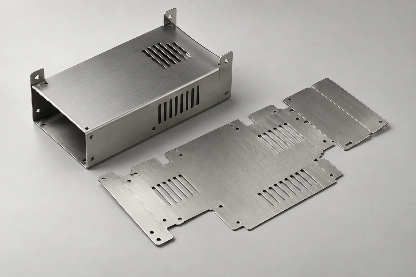
Generated sheet-part design reference, not an actual finished sample, measured result or verified equipment capability.
01 / FUNCTIONAL SHAPE
Angle and radius are only part of the requirement. The important result may be a mounting interface, enclosure fit or assembled clearance.
Mark hole locations, contact faces and datums. Provide mating geometry so the final formed relationship can be checked meaningfully.
Show flanges, closures and access constraints. Review bends and tool interference before assuming the entire shape can be formed unchanged.
Map visible bend regions, traces and permitted marks. Agree the stock surface and final finish rather than expecting every bend to be cosmetically identical.
02 / TOOLING REVIEW
Grade, thickness, geometry and responsible tooling affect the proposed route. No universal minimum radius or maximum size is stated.
Specify functional geometry and acceptable alternatives. Review any proposed change against mating fit, appearance and the drawing.
Identify short, obstructed or returning features. Ask whether the proposed sequence and tools can reach the required regions.
Highlight holes, slots, reliefs or tabs near bends. Review possible shape effects and the final acceptance need.
Define how the part is located across operations and which relationships matter after forming. A flat blank measurement may not prove the assembled requirement.
03 / STOCK & DEFINITION
Material and geometry information must describe the same revision. The offered preparation should preserve the controlling final shape.
| Input | Provide | Resolve |
|---|---|---|
| Stock | Grade, thickness and condition. | Offered supply and allowed alternatives. |
| Formed CAD | Units, revision and final shape. | Critical interfaces and permitted changes. |
| Drawing | Datums, bend relationships and finish. | Measurement state and precedence. |
| Flat pattern | Any governing outline or preparation assumptions. | Consistency with the reviewed forming route. |
04 / OPERATION ORDER
Forming can interact with joining, inserts or treatment. Review what happens before the part reaches its accepted condition.
Generated sheet geometry concept; it does not prove a bending radius, tool clearance or actual formed dimensions.
Discuss geometry supporting the proposed bends. Added or changed reliefs must be accepted where they affect function or appearance.
Mark contact and visible faces and relevant process-mark limits. Confirm protection and any subsequent finish scope.
Identify joints, hardware or machining needed after forming. Agree responsibility and final-state checks for the complete route.
A different stock, radius or sequence can affect the accepted sample. Record the revised definition and additional evidence required.
05 / FINAL CHECKS
Dimensions and appearance need a stated reference and condition. Agree sample selection and methods for the actual delivery.
| Area | Agree | Connect to |
|---|---|---|
| Position | Critical holes, faces and locating datums. | Final formed geometry. |
| Shape | Important flange and bend relationships. | Method, state and revision. |
| Surface | Permitted marks, edge and finish condition. | Accepted stock and process scope. |
| Assembly | Mating reference and relevant clearance. | Approved delivered configuration. |
06 / QUOTATION
Preparation, tool access, secondary work and inspection assumptions can differ. Keep them visible before accepting price or timing.
Files, stock, final interfaces, radius requirements or flexibility, surface map, sample and production quantities and destination.
Ask what tooling, sequence, relief or geometry changes are proposed. Confirm included edge completion, finish and evidence.
Record changes and sample scope before release. Numerical capabilities, MOQ, tooling availability and schedule must be confirmed for the actual proposal.
07 / QUESTIONS
Use the delivered interface to guide stock and tooling decisions.
No universal value is asserted. Review exact stock, thickness, geometry and the responsible forming route.
It may not. Provide the formed drawing and datums and state which definition governs.
Feature-to-bend relationships require review for the actual geometry and stock. Mark the final requirement and important interfaces.
Review its effect on access, references, surfaces and final fit before accepting the change.
No default all-feature scope is promised. Agree methods, quantities, features and records.
PREPARE THE NEXT DECISION
Include CAD and drawing, material/thickness, bend intent and permitted alternatives, critical holes or faces, final datums, surface requirements, quantities and destination.
sales@keepwinco.comAn enquiry starts a team review. Material, fit, quantity, schedule, operation responsibility and supporting records are confirmed in the proposal; this form does not create an order or an instant price.
Start with what you know. Review your details before sending; no account needed.
Start parts inquiry →Your project is saved securely only when submission succeeds.
General material context only; external references do not certify a finished KeepWin product.
Protolabs - bend and flat-pattern relationships ↗Protolabs - forming feature review ↗