
Form and assembly
Identify interfaces, holes, clearances and the mating references. Decide whether the sample checks packaging space, assembly sequence or a final fit requirement.
PARTNER-SUPPORTED MANUFACTURING / FILAMENT PRINTING
Review a filament-built part around the features that carry load, assemble or remain visible. Keep the exact material, build arrangement, support removal and sample purpose connected before approving the proposed route.
KeepWin coordinates partner-supported review. Exact material, responsible operations, process availability, dimensions, inspection, commercial quantities and timing are confirmed in the project proposal; no universal capability or certification is promised.
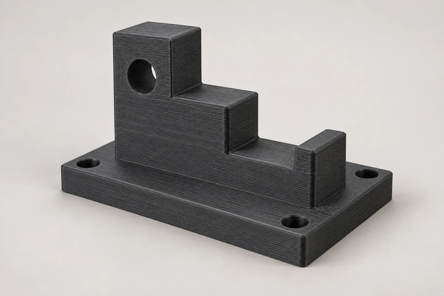
Existing generated filament-printing concept. It illustrates layered geometry, not a specific material grade, measured strength or a customer production job.
01 / USE & ALTERNATIVES
A filament prototype can address geometry, handling or assembly. Its suitability for service use needs a different evaluation from visual approval.
Identify interfaces, holes, clearances and the mating references. Decide whether the sample checks packaging space, assembly sequence or a final fit requirement.
Describe clamping, contact, repeated movement and environment. Review the exact material and build configuration against the use rather than assuming every printed fixture is durable.
Mark visible faces and layer-mark limits. Compare finishing effort with another printing route if the primary decision is surface appearance.
02 / LAYER DIRECTION
A build arrangement affects layer direction, support contact and visible surfaces. Mark the priorities so an easier build does not silently change the functional evaluation.
Show clips, tabs, screw bosses and clamping regions. Describe the direction and repeat use expected so the proposed sample can be assessed appropriately.
Mark which faces locate the assembly and where holes or contact surfaces govern acceptance. Confirm the state in which those features are measured.
Identify faces where marks are unacceptable and spaces that may trap support. Discuss a revised arrangement before changing the geometry.
Record the approved balance between appearance, support access, geometry and functional evaluation. A layer-height setting alone does not define the complete result.
03 / MATERIAL IDENTITY
Two materials sharing a broad family name may differ in formulation, reinforcement or supplied condition. Exact identity and permitted alternatives help control later repeats.
| Decision | Provide | Review |
|---|---|---|
| Identity | Exact product or required grade and color. | Offered material and allowed substitutions. |
| Use environment | Temperature, moisture, light or chemical exposure. | Applicable material and finished-part evidence. |
| Reinforcement | Whether a filled formulation is required. | Compatibility with geometry, route and acceptance. |
| Documentation | Needed identity or traceability records. | Availability and scope for the actual supply. |
04 / SUPPORTS & DETAILS
Overhangs, cavities and fragile details should be reviewed with the actual support strategy. Do not assume all support material can be removed from every enclosed feature.
Show internal channels and enclosed spaces. Identify access for support removal and any required verification of the internal path.
Highlight delicate walls, long spans and sharp transitions. Ask for process-specific review without applying a single wall value to all materials.
State whether the feature is printed, finished secondarily or uses an insert. Review access, assembly intent and final-state checks.
Approve added openings, split parts, radii or altered support-contact zones explicitly. Record their effect on the original sample purpose.
05 / DELIVERED CONDITION
Support removal, sanding, coating or secondary work can alter the delivered geometry. Separate required completion from optional cosmetic refinement.
Existing generated FDM part concept; not a before-and-after finish comparison or measured surface sample.
| Scope | Define | Acceptance question |
|---|---|---|
| Cleaned print | Support-removal scope and permitted marks. | Are critical openings and features usable? |
| Cosmetic refinement | Visible faces, texture or color reference. | Does the physical sample meet the agreed appearance? |
| Functional secondary work | Inserts, mating surfaces or holes requiring review. | Are the delivered interfaces checked after the work? |
| Repeat parts | Controlled material, files, build and surface scope. | Does the approved sample represent this configuration? |
06 / SAMPLE & QUOTATION
Include preparation, supports, post-processing and evidence alongside quantity. Unit price without the delivered condition can hide a different scope.
Files, material, use and important interfaces.
Orientation, support access and alternatives.
Agreed fit, appearance and functional questions.
Revision, processing and evidence scope.
Checks, identity, packing and records.
Send model units, drawing if available, quantities, variants, destination and desired milestones. Mark exact material requirements and acceptable alternatives.
Ask which operations, sample checks, reports and secondary work are included. Confirm responsible partners, minimum quantities and schedule assumptions for the actual project.
07 / QUESTIONS
Start from the part requirement and keep the processed state visible.
No universal result follows from one setting. Review geometry, orientation, exact material, processing and the acceptance method together.
Availability and route suitability require confirmation for the offered project. A polymer family name is not a stock list.
No such promise is made. Review access, geometry and the actual support strategy before accepting the build.
It depends on the interface and requirement. Define the final fit, any secondary work and the checks needed after processing.
Only within the agreed scope. Record the purpose, material and configuration and resolve remaining functional questions before extending approval.
PREPARE THE NEXT DECISION
Include CAD units and revision, loaded interfaces, assembly direction, exact filament if required, support-mark limits, sample purpose, quantities and destination.
sales@keepwinco.comAn enquiry starts a team review. Material, fit, quantity, schedule, operation responsibility and supporting records are confirmed in the proposal; this form does not create an order or an instant price.
Start with what you know. Review your details before sending; no account needed.
Start parts inquiry →Your project is saved securely only when submission succeeds.
General material context only; external references do not certify a finished KeepWin product.
Stratasys - support-access design context ↗BigRep - orientation review context ↗